Concept explainers
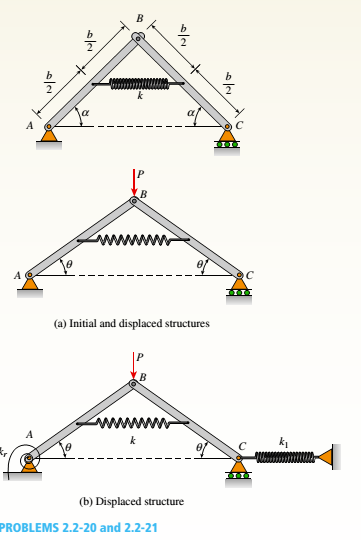
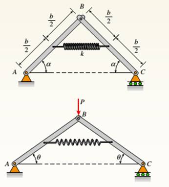
A framework ABC consists of two rigid bars AB and BC. Each having a length b (see the first part of the figure part a). The bars have pin connections at A, B, and C and are joined by a spring of stiffness k. The spring is attached at the midpoints of the bars. The framework has a pin support at A and a roller support al C, and the bars are at an angle a to the horizontal.
When a vertical load P is applied at joint B (see the second part of the figure part a.) the roller support C moves to the right, the spring is stretched, and the angle of the bars decreases from a to the angle ??.
(a) Determine the angle 0 and the increase S in the distance between points A and C. Also find reactions at A and C. (Use the following data: b = 200 mm. ft = 3.2 kN/m. a = 45°. and
P = 50 N.)
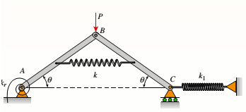
(b) Repeat part (a) if a translational spring kt= kll is added at C and a rotational spring kr= kb-l2 is added at A (see figure pan b).

(a)
The angle
Answer to Problem 2.2.20P
The angle
The distance between points A and C,
The reaction at support C
The reaction at support A
Explanation of Solution
Given information:
The length of the rigid bars b = 200 mm
The stiffness of the spring k = 3.2 kN/m
The angle of bars from the horizontal =
The valueof load P = 50 N

Figure: Initial and displaced positions of the framework.
Calculation:
Let us consider the structure in its displaced position. Let us use the free body diagrams of left-hand bars and right-hand bars.
From the free body diagram of left-hand bar,
Reaction at support A,
From the free body diagram of right-hand bar,
From overall FBD of the beams,
We have two expressions for Rc, equating both of the expressions and then substitute expressions for L2, kr, k1, h and
Now,
Let us substitute the numerical values of variables and calculate the values of angle
Solving the above equation gives,
Now, let us compute the reactions at point C and A.
The reaction at point C
And the reaction at point A is
Conclusion: Thus, the angle
The distance between points A and C,
The reaction at support C
The reaction at support A
(b)
The angle
Answer to Problem 2.2.20P
The angle
The distance between points A and C,
The reaction at support C
The reaction at support A
The moment reaction at point A is
Explanation of Solution
Given information:
The length of the rigid bars b = 200 mm
The stiffness of the spring k = 3.2 kN/m
The angle of bars from the horizontal =
The value of load P = 50 N

Figure: Initial and displaced positions of the framework.
Calculation:
Let us consider the structure in its displaced position. Let us use the free body diagrams of left-hand bars and right-hand bars.
From the free body diagram of left-hand bar,
Reaction at support A,
From the free body diagram of right-hand bar,
From overall FBD of the beams,
We have two expressions for Rc, equating both of the expressions and then substitute expressions for L2, kr, k1, h and
Now,
Let us substitute the numerical values of variables and calculate the values of angle
Solving the above equation gives,
Now, let us compute the reactions at point C and A.
The reaction at point C,
And the reaction at point A is
Now, moment reaction at point A is,
Conclusion: Thus, the angle
The distance between points A and C,
The reaction at support C
The reaction at support A
The moment reaction at point A is
Want to see more full solutions like this?
Chapter 2 Solutions
Mechanics of Materials (MindTap Course List)
- (Read image)arrow_forward(Read Image)arrow_forwardM16x2 grade 8.8 bolts No. 25 C1- Q.2. The figure is a cross section of a grade 25 cast-iron pressure vessel. A total of N, M16x2.0 grade 8.8 bolts are to be used to resist a separating force of 160 kN. (a) Determine ks, km, and C. (b) Find the number of bolts required for a load factor of 2 where the bolts may be reused when the joint 19 mm is taken apart. (c) with the number of bolts obtained in (b), determine the realized load factor for overload, the yielding factor of safety, and the separation factor of safety. 19 mmarrow_forward
- Problem4. The thin uniform disk of mass m = 1-kg and radius R = 0.1m spins about the bent shaft OG with the angular speed w2 = 20 rad/s. At the same time, the shaft rotates about the z-axis with the angular speed 001 = 10 rad/s. The angle between the bent portion of the shaft and the z-axis is ẞ = 35°. The mass of the shaft is negligible compared to the mass of the disk. a. Find the angular momentum of the disk with respect to point G, based on the axis orientation as shown. Include an MVD in your solution. b. Find the angular momentum of the disk with respect to point O, based on the axis orientation as shown. (Note: O is NOT the center of fixed-point rotation.) c. Find the kinetic energy of the assembly. z R R 002 2R x Answer: H = -0.046ĵ-0.040 kg-m²/sec Ho=-0.146-0.015 kg-m²/sec T 0.518 N-m =arrow_forwardProblem 3. The assembly shown consists of a solid sphere of mass m and the uniform slender rod of the same mass, both of which are welded to the shaft. The assembly is rotating with angular velocity w at a particular moment. Find the angular momentum with respect to point O, in terms of the axes shown. Answer: Ñ。 = ½mc²wcosßsinßĵ + (}{mr²w + 2mb²w + ½ mc²wcos²ß) k 3 m r b 2 C لا marrow_forwardOnly question 2arrow_forward
- Only question 1arrow_forwardOnly question 3arrow_forwardI have Euler parameters that describe the orientation of N relative to Q, e = -0.7071*n3, e4 = 0.7071. I have Euler parameters that describe the orientation of U relative to N, e = -1/sqrt(3)*n1, e4 = sqrt(2/3). After using euler parameter rule of successive rotations, I get euler parameters that describe the orientation of U relative to Q, e = -0.4082*n1 - 0.4082*n2 - 0.5774*n3. I need euler parameters that describe the orientation of U relative to Q in vector basis of q instead of n. How do I get that?arrow_forward
- Describe at least 4 processes in engineering where control charts are (or should be) appliedarrow_forwardDescribe at least two (2) processes where control charts are (or should be) applied.arrow_forwardProblem 3: A cube-shaped spacecraft is in a circular Earth orbit. Let N (n,) be inertial and the spacecraft is denoted S (ŝ₁). The spacecraft is described such that ¯½º = J ŝ₁ŝ₁ + J ŝ₂§₂ + J §¸Ŝ3 Location of the spacecraft in the orbit is determined by the orbit-fixed unit vectors ê, that are oriented by the angle (Qt), where is a constant angular rate. 52 €3 3> 2t 55 Λ Из At the instant when Qt = 90°, the spacecraft S is oriented relative to the orbit such that 8₁ = 0° Space-three 1-2-3 angles 0₂ = 60° and ES = $₂ rad/s 0₁ = 135° (a) At this instant, determine the direction cosine matrix that describes the orientation of the spacecraft with respect to the inertial frame N.arrow_forward
 Mechanics of Materials (MindTap Course List)Mechanical EngineeringISBN:9781337093347Author:Barry J. Goodno, James M. GerePublisher:Cengage Learning
