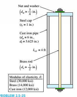
A capped cast-iron pipe is compressed by a brass rod, as shown. The mil is turned until it is just snug, then add an additional quarter turn to pre-compress the cast-iron pipe. The pitch of the threads of the bolt ap = 52 mils (a mil is one-thousandth of an inch). Use the numerical properties provided.
(a) What stresses a and arwill be produced in the cast-iron pipe and brass rod. respectively, by the additional quarter turn of the nut?
(b) Find the bearing stress ahbeneath the washer and the shear stress t(in the steel cap.

(a)
The stress produced in pipe and bar.
Answer to Problem 2.5.25P
The stress produced in pipe is=
The stress produced in bar is =
Explanation of Solution
Given information:
The pitch of the bolt is
Write the expression for area of rod.
Here, area of rod is
Write the expression for area of pipe.
Here, area of pipe is
Write the expression for displacement between cut ends.
Here, displacement between cut ends of the rod is
Write the expression for relative displacement between cut ends.
Here, relative displacement between cut ends is
Write the compatibility Equation for displacement.
Write the expression for force on rod.
Here, force on rod is
Write the expression for force on pipe.
Here, force on pipe is
Write the expression for stress on cast iron pipe.
Here, stress on cast iron pipe is
Write the expression for stress in rod.
Here, stress on rod is
Calculation:
Substitute
Substitute
Substitute
Substitute
Substitute
Substitute
Substitute
Substitute
Substitute
Conclusion:
The stress produced in pipe is =
The stress produced in bar is =
(b)
The bearing stress in cap.
The shearing stress in the cap.
Answer to Problem 2.5.25P
The bearing stress in cap is =
The shearing stress in the cap is =
Explanation of Solution
Given information:
The pitch of the bolt is
Write the expression for area of cap.
Here, area of cap is
Write the expression for bearing stress on cap.
Here, bearing stress on cap is
Write the expression for shearing stress on the cap.
Here, shearing stress on the cap is
Calculation:
Substitute
Substitute
Substitute
Conclusion:
The bearing stress in cap is =
The shearing stress in the cap is =
Want to see more full solutions like this?
Chapter 2 Solutions
Mechanics of Materials (MindTap Course List)
- A ship of 10 000 tonne displacement has a waterplanearea of 1300 m2. The ship loads in water of 1.010 t/m3 andmoves into water of 1.026 t/m3. Find the change in meandraughtarrow_forwardA ship of 7000 tonne displacement has a waterplane areaof 1500 m2. In passing from sea water into river water of1005 kg/m3 there is an increase in draught of 10 cm. Find the Idensity of the sea water.arrow_forwardA ship has 300 tonne of cargo in the hold, 24 m forward ofmidships. The displacement of the vessel is 6000 tonne and its centre of gravity is 1.2 m forward of midships.Find the new position of the centre of gravity if this cargo ismoved to an after hold, 40 m from midshipsarrow_forward
- Sketch and describe how ships are supported in dry dock. When and where does the greatest amount of stresses occur?arrow_forwardSketch and desribe a balanced rudder and how it is suspendedarrow_forwardA ship 140 m long and 18 m beam floats at a draught of9 m. The immersed cross-sectionai areas at equai intervais are 5,60, 116, 145, 152, 153, 153, 151, 142, 85 and 0 m2 respectively.Calculate:(a) displacement(b) block coefficient(c) midship section area coefficient(d) prismatic coefficient.arrow_forward
- A steamer has waterplane area 1680m2 recorded in water with relative denisty 1.013. Displacement = 1200 t, calculate difference in draught in salwater reltive denisity 1.025.arrow_forwardrelative velocity 11.72 m/s is correct, need help finding the angle pleasearrow_forwardDetermine the distance between the two automobiles 2 s after A has passed through the intersection.arrow_forward
- A box barge 65 m long and 12 m wide floats at a draught of5.5 m in sea water. Calculate:(a) the displacement of the barge,(b) its draught in fresh waterarrow_forwardwhat is the angle of the velocity of block B? velocity is 7.46 in/s Determine the acceleration and angle of block B. (Round the acceleration value to three decimal places.)arrow_forwardDetermine the relative velocity of B with respect to A.arrow_forward
 Mechanics of Materials (MindTap Course List)Mechanical EngineeringISBN:9781337093347Author:Barry J. Goodno, James M. GerePublisher:Cengage Learning
