
Power System Analysis and Design (MindTap Course List)
6th Edition
ISBN: 9781305632134
Author: J. Duncan Glover, Thomas Overbye, Mulukutla S. Sarma
Publisher: Cengage Learning
expand_more
expand_more
format_list_bulleted
Concept explainers
Videos
Textbook Question
Chapter 2, Problem 2.31P
Consider two interconnected voltage sources connected by a line of impedance
(a) Obtain expressions for
(b) Determine the maximum power transfer and the condition for it to 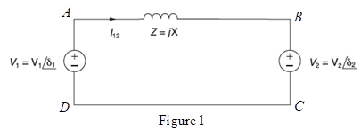
Expert Solution & Answer

Trending nowThis is a popular solution!

Students have asked these similar questions
Answer the following questions:
1- Write radiation resistance (R.) equation for infinitesimal dipole antenna.
2- Write the angle expression form of first null beam width (FNBW) for 2/2 dipole.
3- Define the Directivity of antenna.
4- Write radar cross section equation.
5- Write the input impedance (Z) expression of lossless transmission line.
The input reactance of an infinitesimal linear dipole of length 1/60 and radius
a = x/200 is given by
[In(/2a) - 11
X-120-
tan(kl/2)
Assuming the wire of the dipole is copper with a conductivity of 5.7 × 10'S/m.
determine at f = 1 GHz the
(a) loss resistance
(b) radiation resistance
(c) radiation efficiency
input impedance
Q4- a) For the block diagram of control system shown below with its unit step response. Determine
(K, a,damping ration, Maximum overshoot, Wn, Wd,ẞ, ts, tp, td, tr, and overall transfer function?
C(1) ↑
1.4
1.2
1
0.8
0.6
0.4
0.2
R(s)
E(s)
K
C(s)
$(s + α)
0.05
0.1
0.15
0.2
+2%
-2%
Chapter 2 Solutions
Power System Analysis and Design (MindTap Course List)
Ch. 2 - The rms value of v(t)=Vmaxcos(t+) is given by a....Ch. 2 - If the rms phasor of a voltage is given by V=12060...Ch. 2 - If a phasor representation of a current is given...Ch. 2 - Prob. 2.4MCQCh. 2 - Prob. 2.5MCQCh. 2 - Prob. 2.6MCQCh. 2 - Prob. 2.7MCQCh. 2 - Prob. 2.8MCQCh. 2 - Prob. 2.9MCQCh. 2 - The average value of a double-frequency sinusoid,...
Ch. 2 - The power factor for an inductive circuit (R-L...Ch. 2 - The power factor for a capacitive circuit (R-C...Ch. 2 - Prob. 2.13MCQCh. 2 - The instantaneous power absorbed by the load in a...Ch. 2 - Prob. 2.15MCQCh. 2 - With generator conyention, where the current...Ch. 2 - Consider the load convention that is used for the...Ch. 2 - Prob. 2.18MCQCh. 2 - The admittance of the impedance j12 is given by...Ch. 2 - Consider Figure 2.9 of the text, Let the nodal...Ch. 2 - The three-phase source line-to-neutral voltages...Ch. 2 - In a balanced three-phase Y-connected system with...Ch. 2 - In a balanced system, the phasor sum of the...Ch. 2 - Consider a three-phase Y-connected source feeding...Ch. 2 - For a balanced- load supplied by a balanced...Ch. 2 - A balanced -load can be converted to an...Ch. 2 - When working with balanced three-phase circuits,...Ch. 2 - The total instantaneous power delivered by a...Ch. 2 - The total instantaneous power absorbed by a...Ch. 2 - Under balanced operating conditions, consider the...Ch. 2 - One advantage of balanced three-phase systems over...Ch. 2 - While the instantaneous electric power delivered...Ch. 2 - Given the complex numbers A1=630 and A2=4+j5, (a)...Ch. 2 - Convert the following instantaneous currents to...Ch. 2 - The instantaneous voltage across a circuit element...Ch. 2 - For the single-phase circuit shown in Figure...Ch. 2 - A 60Hz, single-phase source with V=27730 volts is...Ch. 2 - (a) Transform v(t)=75cos(377t15) to phasor form....Ch. 2 - Let a 100V sinusoidal source be connected to a...Ch. 2 - Consider the circuit shown in Figure 2.23 in time...Ch. 2 - For the circuit shown in Figure 2.24, compute the...Ch. 2 - For the circuit element of Problem 2.3, calculate...Ch. 2 - Prob. 2.11PCh. 2 - The voltage v(t)=359.3cos(t)volts is applied to a...Ch. 2 - Prob. 2.13PCh. 2 - A single-phase source is applied to a...Ch. 2 - Let a voltage source v(t)=4cos(t+60) be connected...Ch. 2 - A single-phase, 120V(rms),60Hz source supplies...Ch. 2 - Consider a load impedance of Z=jwL connected to a...Ch. 2 - Let a series RLC network be connected to a source...Ch. 2 - Consider a single-phase load with an applied...Ch. 2 - A circuit consists of two impedances, Z1=2030 and...Ch. 2 - An industrial plant consisting primarily of...Ch. 2 - The real power delivered by a source to two...Ch. 2 - A single-phase source has a terminal voltage...Ch. 2 - A source supplies power to the following three...Ch. 2 - Consider the series RLC circuit of Problem 2.7 and...Ch. 2 - A small manufacturing plant is located 2 km down a...Ch. 2 - An industrial load consisting of a bank of...Ch. 2 - Three loads are connected in parallel across a...Ch. 2 - Prob. 2.29PCh. 2 - Figure 2.26 shows three loads connected in...Ch. 2 - Consider two interconnected voltage sources...Ch. 2 - Prob. 2.35PCh. 2 - Prob. 2.36PCh. 2 - Prob. 2.37PCh. 2 - Prob. 2.38PCh. 2 - Prob. 2.39PCh. 2 - A balanced three-phase 240-V source supplies a...Ch. 2 - Prob. 2.41PCh. 2 - A balanced -connected impedance load with (12+j9)...Ch. 2 - A three-phase line, which has an impedance of...Ch. 2 - Two balanced three-phase loads that are connected...Ch. 2 - Two balanced Y-connected loads, one drawing 10 kW...Ch. 2 - Three identical impedances Z=3030 are connected in...Ch. 2 - Two three-phase generators supply a three-phase...Ch. 2 - Prob. 2.48PCh. 2 - Figure 2.33 gives the general -Y transformation....Ch. 2 - Consider the balanced three-phase system shown in...Ch. 2 - A three-phase line with an impedance of...Ch. 2 - A balanced three-phase load is connected to a...Ch. 2 - What is a microgrid?Ch. 2 - What are the benefits of microgrids?Ch. 2 - Prob. CCSQCh. 2 - Prob. DCSQ
Knowledge Booster


Learn more about
Need a deep-dive on the concept behind this application? Look no further. Learn more about this topic, electrical-engineering and related others by exploring similar questions and additional content below.Similar questions
- Determine the power radiated for the antenna has the following specifications (48 ohm radiation resistance, 2 ohm loss resistance and 50 ohms reactance) connected to generator with 12 V open circuit and internal impedance 50 ohm via à long transmission line with 100 ohm characteristic impedance.arrow_forwardDon't use ai to answer I will report you answerarrow_forwardDon't use ai to answer I will report you answerarrow_forward
- Don't use ai to answer I will report you answerarrow_forwardThe former expert solved the question, but I didn't understand how he simplified the fractions. A communication satellite is in stationary (synchronous) orbit about the carch (assume altitude of 22.300 statute miles). Its transmitter generates 8.0 W. Assume the transmit- ting antenna is isotropic. Its signal is received by the 210-ft diameter tracking parabo- loidal antenna on the earth at the NASA tracking station at Goldstone, California. Also assume no resistive loss in either antenna, perfect polarization match, and perfect impedance match at both antennas. At a frequency of 2 GHz, determine the: (a) power density (in watts/m²) incident on the receiving antenna. (b) power received by the ground-based antenna whose gain is 60 dB.arrow_forwardDon't use ai to answer I will report you answerarrow_forward
- A communication satellite is in stationary (synchronous) orbit about the earch (assume altitude of 22.300 statute miles). Its transmitter generates 8.0 W. Assume the transmit- ting antenna is isotropic. Its signal is received by the 210-ft diameter tracking parabo- loidal antenna on the earth at the NASA tracking station at Goldstone, California. Also assume no resistive loss in either antenna, perfect polarization match, and perfect impedance match at both antennas. At a frequency of 2 GHz. determine the: (a) power density (in watts/m²) incident on the receiving antenna. (b) power received by the ground-based antenna whose gain is 60 dB.arrow_forwardDon't use ai to answer I will report you answerarrow_forwardA plane wave traveling in z-direction through a medium with &=8, μ-2 and has the electric and magnetic field intensity at z=0 shown in Fig. 6.1 and Fig. 6.2, respectively. Utilize the provided information to find the following: (a) w (b) The intrinsic impedance of the medium © B (d) a (e) The expression of the magnetic field intensity, H (f) The time-average power carried by the wave Magnetic Field Intensity (mA/m) Electric Field Intensity (V/m) 0.5 0.4- 0.3 0.2 ཧཱུྃ༔ཤྲུསྦྱ ཌུ ཋ ; སྟྲི " ° ཝཱ 0.1 -0.5 Ex -2.0 -1.5 -1.0 -0.5 0.0 0.5 1.0 1.5 Fig 6.2 Hy 2.0 Time (ns)². -2.0 -1.5 -1.0 -0.5 0.0; 0.5 1.0 Time (ns) 2.0 0.083 ns or 0.0415 Tarrow_forward
arrow_back_ios
SEE MORE QUESTIONS
arrow_forward_ios
Recommended textbooks for you
 Power System Analysis and Design (MindTap Course ...Electrical EngineeringISBN:9781305632134Author:J. Duncan Glover, Thomas Overbye, Mulukutla S. SarmaPublisher:Cengage Learning
Power System Analysis and Design (MindTap Course ...
Electrical Engineering
ISBN:9781305632134
Author:J. Duncan Glover, Thomas Overbye, Mulukutla S. Sarma
Publisher:Cengage Learning
Maximum Power Transfer Theorem Using Nodal Analysis & Thevenin Equivalent Circuits; Author: The Organic Chemistry Tutor;https://www.youtube.com/watch?v=8CA6ZNXgI-Y;License: Standard Youtube License