
Concept explainers
Videos
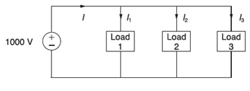
Figure 2.26 shows three loads connected in parallel across a
Load 1: Inductive load,
Load 2: Capacitive load,
Load 3: Resistive load,
(a) Determine the total kW, kvar, kva, and supply power factor.
(b) In order to improve the power factor to 0.8 lagging. a capacitor of negligible resistance is connected in parallel with the above loads. Find the kvar rating of that capacitor and the capacitance in
Comment on the magnitude of the supply current after adding the capacitor.

Trending nowThis is a popular solution!

Chapter 2 Solutions
Power System Analysis and Design (MindTap Course List)


- 3A) Generate a hash table for the following values: 11, 9, 6, 28, 19, 46, 34, 14. Assume the table size is 9 and the primary hash function is h(k) = k % 9. i) Hash table using quadratic probing ii) Hash table with a secondary hash function of h2(k) = 7- (k%7) 3B) Demonstrate with a suitable example, any three possible ways to remove the keys and yet maintaining the properties of a B-Tree. 3C) Differentiate between Greedy and Dynamic Programming.arrow_forwardWhat are the charts (with their title name) that could be use to illustrate the data? Please give picture examples.arrow_forwardA design for a synchronous divide-by-six Gray counter isrequired which meets the following specification.The system has 2 inputs, PAUSE and SKIP:• While PAUSE and SKIP are not asserted (logic 0), thecounter continually loops through the Gray coded binarysequence {0002, 0012, 0112, 0102, 1102, 1112}.• If PAUSE is asserted (logic 1) when the counter is onnumber 0102, it stays here until it becomes unasserted (atwhich point it continues counting as before).• While SKIP is asserted (logic 1), the counter misses outodd numbers, i.e. it loops through the sequence {0002,0112, 1102}.The system has 4 outputs, BIT3, BIT2, BIT1, and WAITING:• BIT3, BIT2, and BIT1 are unconditional outputsrepresenting the current number, where BIT3 is the mostsignificant-bit and BIT1 is the least-significant-bit.• An active-high conditional output WAITING should beasserted (logic 1) whenever the counter is paused at 0102.(a) Draw an ASM chart for a synchronous system to providethe functionality described above.(b)…arrow_forward
- S A B D FL I C J E G H T K L Figure 1: Search tree 1. Uninformed search algorithms (6 points) Based on the search tree in Figure 1, provide the trace to find a path from the start node S to a goal node T for the following three uninformed search algorithms. When a node has multiple successors, use the left-to-right convention. a. Depth first search (2 points) b. Breadth first search (2 points) c. Iterative deepening search (2 points)arrow_forwardWe want to get an idea of how many tickets we have and what our issues are. Print the ticket ID number, ticket description, ticket priority, ticket status, and, if the information is available, employee first name assigned to it for our records. Include all tickets regardless of whether they have been assigned to an employee or not. Sort it alphabetically by ticket status, and then numerically by ticket ID, with the lower ticket IDs on top.arrow_forwardFigure 1 shows an ASM chart representing the operation of a controller. Stateassignments for each state are indicated in square brackets for [Q1, Q0].Using the ASM design technique:(a) Produce a State Transition Table from the ASM Chart in Figure 1.(b) Extract minimised Boolean expressions from your state transition tablefor Q1, Q0, DISPATCH and REJECT. Show all your working.(c) Implement your design using AND/OR/NOT logic gates and risingedgetriggered D-type Flip Flops. Your answer should include a circuitschematic.arrow_forward
- A controller is required for a home security alarm, providing the followingfunctionality. The alarm does nothing while it is disarmed (‘switched off’). It canbe armed (‘switched on’) by entering a PIN on the keypad. Whenever thealarm is armed, it can be disarmed by entering the PIN on the keypad.If motion is detected while the alarm is armed, the siren should sound AND asingle SMS message sent to the police to notify them. Further motion shouldnot result in more messages being sent. If the siren is sounding, it can only bedisarmed by entering the PIN on the keypad. Once the alarm is disarmed, asingle SMS should be sent to the police to notify them.Two (active-high) input signals are provided to the controller:MOTION: Asserted while motion is detected inside the home.PIN: Asserted for a single clock cycle whenever the PIN has beencorrectly entered on the keypad.The controller must provide two (active-high) outputs:SIREN: The siren sounds while this output is asserted.POLICE: One SMS…arrow_forward4G+ Vo) % 1.1. LTE1 : Q B NIS شوز طبي ۱:۱۷ کا A X حاز هذا على إعجاب Mohamed Bashar. MEDICAL SHOE شوز طبي ممول . اقوى عرض بالعراق بلاش سعر القطعة ١٥ الف سعر القطعتين ٢٥ الف سعر 3 قطع ٣٥ الف القياسات : 40-41-42-43-44- افحص وكدر ثم ادفع خدمة التوصيل 5 الف لكافة محافظات العراق ופרסם BNI SH ופרסם DON JU WORLD DON JU MORISO DON JU إرسال رسالة III Messenger التواصل مع شوز طبي تعليق باسم اواب حمیدarrow_forwardA manipulator is identified by the following table of parameters and variables:a. Obtain the transformation matrices between adjacent coordinate frames and calculate the global transformation matrix.arrow_forward
- Which tool takes the 2 provided input datasets and produces the following output dataset? Input 1: Record First Last Output: 1 Enzo Cordova Record 2 Maggie Freelund Input 2: Record Frist Last MI ? First 1 Enzo Last MI Cordova [Null] 2 Maggie Freelund [Null] 3 Jason Wayans T. 4 Ruby Landry [Null] 1 Jason Wayans T. 5 Devonn Unger [Null] 2 Ruby Landry [Null] 6 Bradley Freelund [Null] 3 Devonn Unger [Null] 4 Bradley Freelund [Null] OA. Append Fields O B. Union OC. Join OD. Find Replace Clear selectionarrow_forwardWhat are the similarities and differences between massively parallel processing systems and grid computing. with referencesarrow_forwardModular Program Structure. Analysis of Structured Programming Examples. Ways to Reduce Coupling. Based on the given problem, create an algorithm and a block diagram, and write the program code: Function: y=xsinx Interval: [0,π] Requirements: Create a graph of the function. Show the coordinates (x and y). Choose your own scale and show it in the block diagram. Create a block diagram based on the algorithm. Write the program code in Python. Requirements: Each step in the block diagram must be clearly shown. The graph of the function must be drawn and saved (in PNG format). Write the code in a modular way (functions and the main part should be separate). Please explain and describe the results in detail.arrow_forward
 Operations Research : Applications and AlgorithmsComputer ScienceISBN:9780534380588Author:Wayne L. WinstonPublisher:Brooks Cole
 C++ for Engineers and ScientistsComputer ScienceISBN:9781133187844Author:Bronson, Gary J.Publisher:Course Technology Ptr
 Systems ArchitectureComputer ScienceISBN:9781305080195Author:Stephen D. BurdPublisher:Cengage Learning
 C++ Programming: From Problem Analysis to Program...Computer ScienceISBN:9781337102087Author:D. S. MalikPublisher:Cengage Learning
 New Perspectives on HTML5, CSS3, and JavaScriptComputer ScienceISBN:9781305503922Author:Patrick M. CareyPublisher:Cengage Learning
 A Guide to SQLComputer ScienceISBN:9781111527273Author:Philip J. PrattPublisher:Course Technology Ptr