
Concept explainers
Videos
An adapted launcher uses a torsional spring about point O to help people with mobility impairments throw a Frisbee®. Just after the Frisbee® leaves the arm, the angular velocity of the throwing arm is 200 rad/s and its acceleration is 10 rad/s2; both are counterclockwise. The rotation point O is located 1 in. from the two sides. Assume that you can model the 2-lb throwing arm as a uniform rectangle. Just after the Frisbee® leaves the arm, determine (a) the moment about O caused by the spring, (b) the forces on the pin at O.
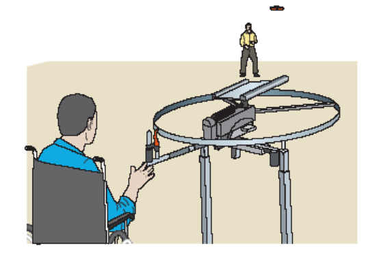
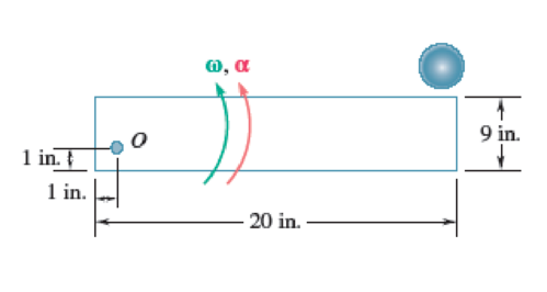
Fig. P16.86
Want to see the full answer?
Check out a sample textbook solution
Chapter 16 Solutions
Vector Mechanics for Engineers: Statics and Dynamics
Additional Engineering Textbook Solutions
Fluid Mechanics: Fundamentals and Applications
Mechanics of Materials (10th Edition)
Automotive Technology: Principles, Diagnosis, And Service (6th Edition) (halderman Automotive Series)
Database Concepts (8th Edition)
Modern Database Management
Computer Science: An Overview (13th Edition) (What's New in Computer Science)


- Design a 4-bar linkage to carry the body in Figure 1 through the two positions P1 and P2 at the angles shown in the figure. Use analytical synthesis with the free choice values z = 1.075, q= 210°, B₂ = −27° for left side and s = 1.24, y= 74°, ½ = − 40° for right side. 1.236 P2 147.5° 210° P1 Figure 1 2.138 Xarrow_forwardcan you explain how in a coordinate frame transformation: v = {v_n}^T {n-hat} and then it was found that {n-hat} = [C]^T {b-hat} so v_n = {v_n}^T [C]^T {b-hat}, how does that equation go from that to this --> v_n = [C]^T v_barrow_forward6) If (k = 0,7 cm) find Imax for figure below. 225mm 100mm ثلاثاء. 100mm 150mm 75mm Ans: Tmax=45:27 N/cm F-400 Narrow_forward
- The man has a weight W and stands halfway along the beam. The beam is not smooth, but the planes at A and B are smooth (and plane A is horizontal). Determine the magnitude of the tension in the cord in terms of W and θ.arrow_forwardDetermine the reactions at the two supports for this plate. Express the reactions in Cartesian vector form.arrow_forwardDetermine the magnitudes of the reactions at the supports for this large plate.arrow_forward
- Only expert should solvearrow_forwardA 15 cm-OD pipe is buried with its centerline 1.25 m below the surface of the ground [k of soil is 0.35 W/(m K)]. An oil having a density of 800 kg/m³ and a specific heat of 2.1 kJ/(kg K) flows in the pipe at 5.6 L/s. Assuming a ground surface temperature of 5°C and a pipe wall temperature of 95°C, estimate the length of pipe in which the oil temperature decreases by 5.5°C. + Tε = 5ºC Z= 1.25 m D= 15 cm 7p=95°Carrow_forwardFind the solution of the following Differential Equations 1) 4y+y=0, y(0)=2, y'(0) = 0. 2) y+y=0, y(0) = A, y'(0) = B. 3) "+2y'-8y=0, y(0)=1, y'(0)=8. 4) y"-2y-3y=0, y(0)=1, y'(0)=7. 5) y"-ky' =0, y(0)=2, y'(0) =k. 6) y+ky'-2k2y=0, y(0)=2, y'(0) = 2k. 7) y'+4y=0, y(0)=2.8 y+y-17sin(21) y(0)=-1. 9) y-y'-6y=0, y(0)=6. y'(0)=13. 10) y-y=0, 11) y"-4y+4y=0, y(0)=4, y'(0) = 0. y(0) = 2.1, y'(0)=3.9 12) y+2y+2y=0, y(0)=1, y'(0)=-3. 13) "+7y+12y=21e", y(0)=3.5, y'(0)=-10. 14) "+9y=10e", y(0)=0. y'(0) = 0. 15) y+3y+2.25y=91³ +64. y(0)=1, y'(0) = 31.5 16) "-6y+5y= 29 cos(21), y(0)=3.2, y'(0) = 6.2 17) y+2y+2y=0, y(0)=0, y'(0)=1. 18) y+2y+17y=0, y(0)=0, y'(0)=12. 19) y-4y+5y=0, y(0)-1, y'(0) 2. 20) 9y-6y+y=0. y(0)=3, y'(0)=1. 21) -2y+10y=0, y(0)=3, y'(0)=3. 22) 4y-4y+37y=0, (0) 3. y(0) 1.5 23) 4y-8y+5y=0, (0)-0, y(0) 1. 24) y+y+1.25y=0, y(0) 1. y'(0) -0.5 25) y+y=2 cos(1). y(0) 2. y'(0) = 0. 26) -4y+3y=0, (0)-3, y'(0) = 7. 27) y+2y+y=e", y(0)-0. y'(0) = 0. 29) 28) y+2y-3y-10sinh(2),…arrow_forward
- Note: Please provide a clear, step-by-step simplified handwritten working out (no explanations!), ensuring it is done without any AI involvement. I require an expert-level answer, and I will assess and rate based on the quality and accuracy of your work and refer to the provided image for more clarity. Make sure to double-check everything for correctness before submitting appreciate your time and effort!. Question:arrow_forward4. Block A and B are two different pieces of wood. Determine the minimum dimension for "a", if the shear stress of the wood is 50Mpa. The thickness of the wood is 30cm. 600N Aarrow_forward1. Determine the reaction force at A. 60 kN 5 B 1 m 1 m- -1 m 4 3 m 30 kN marrow_forward
 Elements Of ElectromagneticsMechanical EngineeringISBN:9780190698614Author:Sadiku, Matthew N. O.Publisher:Oxford University Press
 Mechanics of Materials (10th Edition)Mechanical EngineeringISBN:9780134319650Author:Russell C. HibbelerPublisher:PEARSON
 Thermodynamics: An Engineering ApproachMechanical EngineeringISBN:9781259822674Author:Yunus A. Cengel Dr., Michael A. BolesPublisher:McGraw-Hill Education
 Control Systems EngineeringMechanical EngineeringISBN:9781118170519Author:Norman S. NisePublisher:WILEY
 Mechanics of Materials (MindTap Course List)Mechanical EngineeringISBN:9781337093347Author:Barry J. Goodno, James M. GerePublisher:Cengage Learning
 Engineering Mechanics: StaticsMechanical EngineeringISBN:9781118807330Author:James L. Meriam, L. G. Kraige, J. N. BoltonPublisher:WILEY