
Concept explainers
Videos
The 6-kg rod BC connects a 10-kg disk centered at A to a 5-kg rod CD. The motion of the system is controlled by the couple M applied to disk A. Knowing that at the instant shown disk A has an angular velocity of 36 rad/s clockwise and no angular acceleration, determine (a) the couple M, (b) the components of the force exerted at C on rod BC.
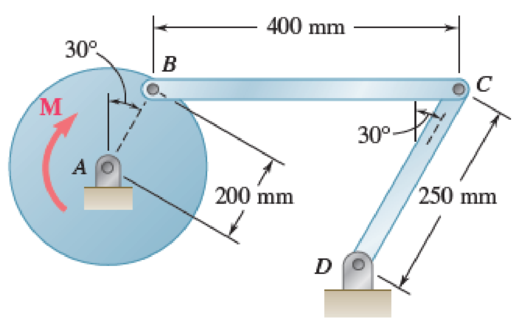
Fig. P16.135 and P16.136
(a)
Find the couple M.
Answer to Problem 16.135P
The couple M is
Explanation of Solution
Given information:
The mass of the rod BC is
The mass of the disk is
The mass of the rod CD is
The angular velocity is
The angular acceleration is
Calculation:
Consider the acceleration due to gravity as
Calculate the velocity of disk AB
Substitute
Calculate the velocity of rod BC
The velocity of disk AB is equal to the velocity of rod BC.
Substitute
Calculate the angular velocity of rod CD
Substitute
Apply the acceleration analysis as shown below.
Calculate the acceleration for disk AB
Substitute
Calculate the acceleration for rod BC
Substitute
Calculate the acceleration for rod CD
Substitute
Equating the components of Equations (1) and (2) as shown below.
Along x component.
Along y component.
Substitute
Calculate the acceleration of the mass centers as shown below.
Calculate the acceleration of mass center for disk AB
Calculate the acceleration of the mass center at P for rod BC
Substitute
Substitute
Calculate the acceleration of the mass center at Q for rod CD
Substitute
Calculate the inertial terms at mass centers as shown below.
The inertia terms at centers are
For disk AB.
For rod BC.
Substitute
For rod CD.
Substitute
Calculate the mass moment of inertia
For disk AB.
Substitute
For rod BC.
Substitute
For rod CD.
Substitute
Calculate the effective couples at mass centers as shown below.
The inertia terms at centers are
For disk AB.
For rod BC.
Substitute
For rod CD.
Substitute
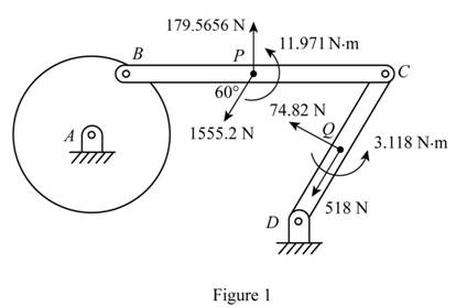
Sketch the effective force and couples on the system as shown in Figure 1.
Sketch the Free Body Diagram of the rod BC as shown in Figure 2.
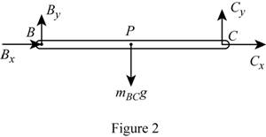
Refer to Figure 2.
Apply the Equilibrium of moment about B as shown below.
Substitute
Sketch the Free Body Diagram of the rod CD as shown in Figure 3.
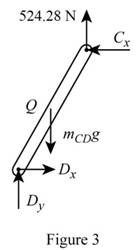
Refer to Figure 3.
Apply the Equilibrium of moment about D as shown below.
Substitute
Sketch the Free Body Diagram of the rod AB and BC as shown in Figure 4.
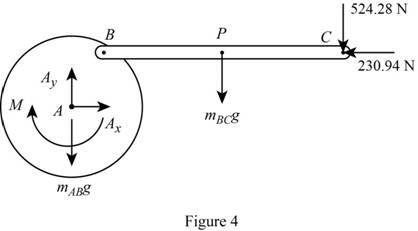
Refer to Figure 4.
Apply the Equilibrium of moment about A as shown below.
Substitute
Therefore, the couple M is
(b)
The components of force exerted at C on rod BC.
Answer to Problem 16.135P
The components of force exerted at C on rod BC is
Explanation of Solution
Given information:
The mass of the rod BC is
The mass of the disk is
The mass of the rod CD is
The angular velocity is
The angular acceleration is
Calculation:
Refer to part (a).
The components of force exerted at C on rod BC along x direction is
The components of force exerted at C on rod BC along y direction is
Therefore, the components of force exerted at C on rod BC is
Want to see more full solutions like this?
Chapter 16 Solutions
Vector Mechanics for Engineers: Statics and Dynamics
Additional Engineering Textbook Solutions
Fluid Mechanics: Fundamentals and Applications
Electric Circuits. (11th Edition)
Experiencing MIS
Starting Out With Visual Basic (8th Edition)
Elementary Surveying: An Introduction To Geomatics (15th Edition)
Thermodynamics: An Engineering Approach


- Problem 1 Consider R has a functional relationship with variables in the form R = K xq xx using show that n ✓ - (OR 1.) = i=1 2 Их Ux2 Ихэ 2 (177)² = ² (1)² + b² (12)² + c² (1)² 2 UR R x2 x3arrow_forward4. Figure 3 shows a crank loaded by a force F = 1000 N and Mx = 40 Nm. a. Draw a free-body diagram of arm 2 showing the values of all forces, moments, and torques that act due to force F. Label the directions of the coordinate axes on this diagram. b. Draw a free-body diagram of arm 2 showing the values of all forces, moments, and torques that act due to moment Mr. Label the directions of the coordinate axes on this diagram. Draw a free body diagram of the wall plane showing all the forces, torques, and moments acting there. d. Locate a stress element on the top surface of the shaft at A and calculate all the stress components that act upon this element. e. Determine the principal stresses and maximum shear stresses at this point at A.arrow_forward3. Given a heat treated 6061 aluminum, solid, elliptical column with 200 mm length, 200 N concentric load, and a safety factor of 1.2, design a suitable column if its boundary conditions are fixed-free and the ratio of major to minor axis is 2.5:1. (Use AISC recommended values and round the ellipse dimensions so that both axes are whole millimeters in the correct 2.5:1 ratio.)arrow_forward
- 1. A simply supported shaft is shown in Figure 1 with w₁ = 25 N/cm and M = 20 N cm. Use singularity functions to determine the reactions at the supports. Assume El = 1000 kN cm². Wo M 0 10 20 30 40 50 60 70 80 90 100 110 cm Figure 1 - Problem 1arrow_forwardPlease AnswerSteam enters a nozzle at 400°C and 800 kPa with a velocity of 10 m/s and leaves at 375°C and 400 kPa while losing heat at a rate of 26.5 kW. For an inlet area of 800 cm2, determine the velocity and the volume flow rate of the steam at the nozzle exit. Use steam tables. The velocity of the steam at the nozzle exit is m/s. The volume flow rate of the steam at the nozzle exit is m3/s.arrow_forward2. A support hook was formed from a rectangular bar. Find the stresses at the inner and outer surfaces at sections just above and just below O-B. -210 mm 120 mm 160 mm 400 N B thickness 8 mm = Figure 2 - Problem 2arrow_forward
- Steam flows steadily through a turbine at a rate of 45,000 lbm/h, entering at 1000 psia and 900°F and leaving at 5 psia as saturated vapor. If the power generated by the turbine is 4.1 MW, determine the rate of heat loss from the steam. The enthalpies are h1 = 1448.6 Btu/lbm and h2 = 1130.7 Btu/lbm. The rate of heat loss from the steam is Btu/s.arrow_forwardThe A/D converter wit the specifications listed below is planned to be used in an environment in which the A/D converter temperature may change by ± 10 °C. Estimate the contributions of conversion and quantization errors to the uncertainty in the digital representation of an analog voltage by the converter. FSO N Linearity error Temperature drift error Analog to Digital (A/D) Converter 0-10 V 12 bits ± 3 bits 1 bit/5 °Carrow_forward6-13. A smooth tube in the form of a circle of radius r rotates in its vertical plane with a constant angular velocity w. The position of a particle of mass m that slides inside the tube is given by the relative coordinate p. Find the differential equation for . e О E g ω Figure P6-13arrow_forward
- Problem 2 Consider the power drawn by a resistance load in a DC circuit. The power is calculated as P = VI or P = 1²R. It is given that the normalized uncertainty or % percentage uncertainty in measurements of I, R, and V are the same. Find the uncertainty in P using the two different expressions for power. Is the uncertainty using the two methods the same? If not, WHY, explain?arrow_forwardA piston–cylinder device contains 3 kg of nitrogen initially at 100 kPa and 25°C. Nitrogen is now compressed slowly in a polytropic process during which PV1.3 = constant until the volume is reduced by one-half. Determine the work done and the heat transfer for this process. The gas constant of N2 is R = 0.2968 kPa·m3/kg·K. The cv value of N2 at the anticipated average temperature of 350 K is 0.744 kJ/kg·K (Table A-2b). The work done for this process is kJ. The heat transfer for this process is kJ.arrow_forwardI tried solving this one but I have no idea where I went wrong can you please help me out with this?arrow_forward
 Elements Of ElectromagneticsMechanical EngineeringISBN:9780190698614Author:Sadiku, Matthew N. O.Publisher:Oxford University Press
 Mechanics of Materials (10th Edition)Mechanical EngineeringISBN:9780134319650Author:Russell C. HibbelerPublisher:PEARSON
 Thermodynamics: An Engineering ApproachMechanical EngineeringISBN:9781259822674Author:Yunus A. Cengel Dr., Michael A. BolesPublisher:McGraw-Hill Education
 Control Systems EngineeringMechanical EngineeringISBN:9781118170519Author:Norman S. NisePublisher:WILEY
 Mechanics of Materials (MindTap Course List)Mechanical EngineeringISBN:9781337093347Author:Barry J. Goodno, James M. GerePublisher:Cengage Learning
 Engineering Mechanics: StaticsMechanical EngineeringISBN:9781118807330Author:James L. Meriam, L. G. Kraige, J. N. BoltonPublisher:WILEY