
Vector Mechanics for Engineers: Statics and Dynamics
11th Edition
ISBN: 9780073398242
Author: Ferdinand P. Beer, E. Russell Johnston Jr., David Mazurek, Phillip J. Cornwell, Brian Self
Publisher: McGraw-Hill Education
expand_more
expand_more
format_list_bulleted
Concept explainers
Videos
Textbook Question
Chapter 16.2, Problem 16.130P
The motion of the uniform slender rod of length L = 0.5 m and mass m = 3 kg is guided by pins at A and B that slide freely in frictionless slots, circular and horizontal, cut into a vertical plate as shown. Knowing that at the instant shown the rod has an angular velocity of 3 rad/s counterclockwise and θ = 30°, determine the reactions at points A and B.
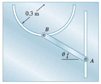
Fig. P16.130
Expert Solution & Answer
Want to see the full answer?
Check out a sample textbook solution
Students have asked these similar questions
I need a mechanical engineering expert to solve this question,no Ai please
Can you give me the meaning of Combination spanner and Give Examples of Spanners
HW8
A shaft fitted with a flywheel rotates at 650 r.p.m. and drives a machine. The
torque of machine varies in a cyclic manner over a period of 2 revolutions. The
torque rises from 650 N-m to 2200 N-m uniformly during 110° and remains
constant for the following 270°. It then falls uniformly to 600 N-m during the next
100° and remains constant for the end cycle, the cycle being repeated thereafter.
Determine the power required to drive the machine and percentage fluctuation in
speed, if the driving torque applied to the shaft is constant and the mass of the
flywheel is 180 kg with radius of gyration of 35 cm.
HW9
Chapter 16 Solutions
Vector Mechanics for Engineers: Statics and Dynamics
Ch. 16.1 - Two pendulums, A and B, with the masses and...Ch. 16.1 - Two pendulums, A and B, with the masses and...Ch. 16.1 - Two solid cylinders, A and B, have the same mass m...Ch. 16.1 - Prob. 16.1FBPCh. 16.1 - Prob. 16.2FBPCh. 16.1 - Prob. 16.3FBPCh. 16.1 - The 400-lb crate shown is lowered by means of two...Ch. 16.1 - A 60-lb uniform thin panel is placed in a truck...Ch. 16.1 - A 60-lb uniform thin panel is placed in a truck...Ch. 16.1 - 16.3 Knowing that the coefficient of static...
Ch. 16.1 - Prob. 16.4PCh. 16.1 - A uniform rod BC of mass 4 kg is connected to a...Ch. 16.1 - A 2000-kg truck is being used to lift a 400-kg...Ch. 16.1 - The support bracket shown is used to transport a...Ch. 16.1 - Prob. 16.8PCh. 16.1 - A 20-kg cabinet is mounted on casters that allow...Ch. 16.1 - Solve Prob. 16.9, assuming that the casters are...Ch. 16.1 - 16.11 A completely filled barrel and its contents...Ch. 16.1 - Prob. 16.12PCh. 16.1 - The retractable shelf shown is supported by two...Ch. 16.1 - Bars AB and BE, each with a mass of 4 kg, are...Ch. 16.1 - At the instant shown, the tensions in the vertical...Ch. 16.1 - Three bars, each of mass 3 kg, are welded together...Ch. 16.1 - Members ACE and DCB are each 600 mm long and are...Ch. 16.1 - 16.18 A prototype rotating bicycle rack is...Ch. 16.1 - Prob. 16.19PCh. 16.1 - The coefficients of friction between the 30-lb...Ch. 16.1 - Prob. 16.21PCh. 16.1 - Prob. 16.22PCh. 16.1 - For a rigid body in translation, show that the...Ch. 16.1 - For a rigid body in centroidal rotation, show that...Ch. 16.1 - It takes 10 min for a 2.4-Mg flywheel to coast to...Ch. 16.1 - The rotor of an electric motor has an angular...Ch. 16.1 - Prob. 16.27PCh. 16.1 - Prob. 16.28PCh. 16.1 - The 100-mm-radius brake drum is attached to a...Ch. 16.1 - The 180-mm-radius disk is at rest when it is...Ch. 16.1 - Solve Prob. 16.30, assuming that the direction of...Ch. 16.1 - In order to determine the mass moment of inertia...Ch. 16.1 - The flywheel shown has a radius of 20 in., a...Ch. 16.1 - Each of the double pulleys shown has a mass moment...Ch. 16.1 - Prob. 16.35PCh. 16.1 - Prob. 16.36PCh. 16.1 - Gear A weighs 1 lb and has a radius of gyration of...Ch. 16.1 - The 25-lb double pulley shown is at rest and in...Ch. 16.1 - A belt of negligible mass passes between cylinders...Ch. 16.1 - Prob. 16.40PCh. 16.1 - Disk A has a mass of 6 kg and an initial angular...Ch. 16.1 - Prob. 16.42PCh. 16.1 - Disk A has a mass mA = 4 kg, a radius rA = 300 mm,...Ch. 16.1 - Disk B is at rest when it is brought into contact...Ch. 16.1 - Prob. 16.45PCh. 16.1 - Prob. 16.46PCh. 16.1 - For a rigid body in plane motion, show that the...Ch. 16.1 - Prob. 16.48PCh. 16.1 - Prob. 16.49PCh. 16.1 - Prob. 16.50PCh. 16.1 - Prob. 16.51PCh. 16.1 - A 250-lb satellite has a radius of gyration of 24...Ch. 16.1 - A rectangular plate of mass 5 kg is suspended from...Ch. 16.1 - Prob. 16.54PCh. 16.1 - A drum with a 200-mm radius is attached to a disk...Ch. 16.1 - A drum with a 200-mm radius is attached to a disk...Ch. 16.1 - The 12-lb uniform disk shown has a radius of r =...Ch. 16.1 - Prob. 16.58PCh. 16.1 - Prob. 16.59PCh. 16.1 - Prob. 16.60PCh. 16.1 - Prob. 16.61PCh. 16.1 - Two uniform cylinders, each of weight W = 14 lb...Ch. 16.1 - Prob. 16.63PCh. 16.1 - Prob. 16.64PCh. 16.1 - A uniform slender bar AB with a mass m is...Ch. 16.1 - Prob. 16.66PCh. 16.1 - 16.66 through 16.68A thin plate of the shape...Ch. 16.1 - 16.66 through 16.68A thin plate of the shape...Ch. 16.1 - A sphere of radius r and mass m is projected along...Ch. 16.1 - Solve Prob. 16.69, assuming that the sphere is...Ch. 16.1 - A bowler projects an 8-in.-diameter ball weighing...Ch. 16.1 - Prob. 16.72PCh. 16.1 - A uniform sphere of radius r and mass m is placed...Ch. 16.1 - A sphere of radius r and mass m has a linear...Ch. 16.2 - A cord is attached to a spool when a force P is...Ch. 16.2 - Prob. 16.5CQCh. 16.2 - Prob. 16.6CQCh. 16.2 - Prob. 16.7CQCh. 16.2 - Prob. 16.5FBPCh. 16.2 - Two identical 4-lb slender rods AB and BC are...Ch. 16.2 - Prob. 16.7FBPCh. 16.2 - Prob. 16.8FBPCh. 16.2 - Show that the couple I of Fig. 16.15 can be...Ch. 16.2 - Prob. 16.76PCh. 16.2 - 16.77 In Prob. 16.76, determine (a) the distance r...Ch. 16.2 - A uniform slender rod of length L = 36 in. and...Ch. 16.2 - In Prob. 16.78, determine (a) the distance h for...Ch. 16.2 - An athlete performs a leg extension on a machine...Ch. 16.2 - Prob. 16.81PCh. 16.2 - Prob. 16.82PCh. 16.2 - Prob. 16.83PCh. 16.2 - A uniform rod of length L and mass m is supported...Ch. 16.2 - 16.84 and 16.85 A uniform rod of length L and mass...Ch. 16.2 - An adapted launcher uses a torsional spring about...Ch. 16.2 - Prob. 16.87PCh. 16.2 - Prob. 16.88PCh. 16.2 - The object ABC consists of two slender rods welded...Ch. 16.2 - A 3.5-kg slender rod AB and a 2-kg slender rod BC...Ch. 16.2 - A 9-kg uniform disk is attached to the 5-kg...Ch. 16.2 - Derive the equation MC=IC for the rolling disk of...Ch. 16.2 - Prob. 16.93PCh. 16.2 - Prob. 16.94PCh. 16.2 - Prob. 16.95PCh. 16.2 - Prob. 16.96PCh. 16.2 - A 40-kg flywheel of radius R = 0.5 m is rigidly...Ch. 16.2 - Prob. 16.98PCh. 16.2 - Prob. 16.99PCh. 16.2 - Prob. 16.100PCh. 16.2 - 16.98 through 16.101 A drum of 60-mm radius is...Ch. 16.2 - Prob. 16.102PCh. 16.2 - 16.102 through 16.105 A drum of 4-in. radius is...Ch. 16.2 - Prob. 16.104PCh. 16.2 - Prob. 16.105PCh. 16.2 - 16.106 and 16.107A 12-in.-radius cylinder of...Ch. 16.2 - 16.106 and 16.107A 12-in.-radius cylinder of...Ch. 16.2 - Gear C has a mass of 5 kg and a centroidal radius...Ch. 16.2 - Two uniform disks A and B, each with a mass of 2...Ch. 16.2 - A single-axis personal transport device starts...Ch. 16.2 - A hemisphere of weight W and radius r is released...Ch. 16.2 - A hemisphere of weight W and radius r is released...Ch. 16.2 - The center of gravity G of a 1.5-kg unbalanced...Ch. 16.2 - A small clamp of mass mB is attached at B to a...Ch. 16.2 - Prob. 16.115PCh. 16.2 - A 4-lb bar is attached to a 10-lb uniform cylinder...Ch. 16.2 - The uniform rod AB with a mass m and a length of...Ch. 16.2 - Prob. 16.118PCh. 16.2 - Prob. 16.119PCh. 16.2 - Prob. 16.120PCh. 16.2 - End A of the 6-kg uniform rod AB rests on the...Ch. 16.2 - End A of the 6-kg uniform rod AB rests on the...Ch. 16.2 - End A of the 8-kg uniform rod AB is attached to a...Ch. 16.2 - The 4-kg uniform rod ABD is attached to the crank...Ch. 16.2 - The 3-lb uniform rod BD is connected to crank AB...Ch. 16.2 - The 3-lb uniform rod BD is connected to crank AB...Ch. 16.2 - The test rig shown was developed to perform...Ch. 16.2 - Solve Prob. 16.127 for = 90. 16.127The test rig...Ch. 16.2 - The 4-kg uniform slender bar BD is attached to bar...Ch. 16.2 - The motion of the uniform slender rod of length L...Ch. 16.2 - At the instant shown, the 20-ft-long, uniform...Ch. 16.2 - Prob. 16.132PCh. 16.2 - Prob. 16.133PCh. 16.2 - The hatchback of a car is positioned as shown to...Ch. 16.2 - The 6-kg rod BC connects a 10-kg disk centered at...Ch. 16.2 - Prob. 16.136PCh. 16.2 - In the engine system shown, l = 250 mm and b = 100...Ch. 16.2 - Solve Prob. 16.137 when = 90. 16.137In the engine...Ch. 16.2 - The 4-lb uniform slender rod AB, the 8-lb uniform...Ch. 16.2 - The 4-lb uniform slender rod AB, the 8-lb uniform...Ch. 16.2 - Two rotating rods in the vertical plane are...Ch. 16.2 - Two rotating rods in the vertical plane are...Ch. 16.2 - Two disks, each with a mass m and a radius r, are...Ch. 16.2 - A uniform slender bar AB of mass m is suspended as...Ch. 16.2 - A uniform rod AB, of mass 15 kg and length 1 m, is...Ch. 16.2 - The uniform slender 2-kg bar BD is attached to the...Ch. 16.2 - Prob. 16.147PCh. 16.2 - Prob. 16.148PCh. 16.2 - Prob. 16.149PCh. 16.2 - Prob. 16.150PCh. 16.2 - (a) Determine the magnitude and the location of...Ch. 16.2 - Prob. 16.152PCh. 16 - A cyclist is riding a bicycle at a speed of 20 mph...Ch. 16 - 16.154 The forklift truck shown weighs 2250 lb and...Ch. 16 - The total mass of the Baja car and driver,...Ch. 16 - Identical cylinders of mass m and radius r are...Ch. 16 - Prob. 16.157RPCh. 16 - The uniform rod AB of weight W is released from...Ch. 16 - Prob. 16.159RPCh. 16 - Prob. 16.160RPCh. 16 - A cylinder with a circular hole is rolling without...Ch. 16 - Prob. 16.162RPCh. 16 - Prob. 16.163RPCh. 16 - The Geneva mechanism shown is used to provide an...
Additional Engineering Textbook Solutions
Find more solutions based on key concepts
A nozzle at A discharges water with an initial velocity of 36 ft/s at an angle with the horizontal. Determine ...
Vector Mechanics For Engineers
Why is the study of database technology important?
Database Concepts (8th Edition)
Assume a telephone signal travels through a cable at two-thirds the speed of light. How long does it take the s...
Electric Circuits. (11th Edition)
17–1C A high-speed aircraft is cruising in still air. How does the temperature of air at the nose of the aircra...
Thermodynamics: An Engineering Approach
How are relationships between tables expressed in a relational database?
Modern Database Management
The solid steel shaft AC has a diameter of 25 mm and is supported by smooth bearings at D and E. It is coupled ...
Mechanics of Materials (10th Edition)
Knowledge Booster


Learn more about
Need a deep-dive on the concept behind this application? Look no further. Learn more about this topic, mechanical-engineering and related others by exploring similar questions and additional content below.Similar questions
- units of h. show all workarrow_forward4. Steam flows steadily through a turbine at a rate of 47,000 lbm/h, entering at 1000 psia and 800°F and leaving at 6 psia as saturated vapor. If the power generated by the turbine is 3.7 MW, determine the rate of heat loss from the steam.arrow_forward3. Water enters the constant 125-mm inside-diameter tubes of a boiler at 7.5 MPa and 60°C and leaves the tubes at 6 MPa and 500°C with a velocity of 75 m/s. Calculate the velocity of the water at the tube inlet and the inlet volume flow rate.arrow_forward
- 2. A piston-cylinder device contains 2.4 kg of nitrogen initially at 120 kPa and 27°C. The nitrogen is now compressed slowly in a polytropic process during which PV1.3 = constant until the volume is reduced by one-half. Determine the work done and the heat transfer for this process.arrow_forward1. 1.25 m³ of saturated liquid water at 225°C is expanded isothermally in a closed system until its quality is 75 percent. Determine the total work produced by this expansion, in kJ.arrow_forwardAn undamped single-degree-of-freedom system is subjected to dynamic excitation as shown in Figure 1.• System properties: m = 1, c = 0, k = (6π)2.• Force excitation: p(t) = posin(ωt) where po = 9 and ω = 2π.• Initial conditions: u(t = 0) = 0 and ̇u(t = 0) = 0.Please, complete Parts (a) through (d) using any computational tool of your preference. The preferred toolis MATLAB. Print and turn in a single pdf file that will include your code/calculations and your plots.(a) Generate the solution using a linear interpolation of the load over each time step (note that hereyou can use the undamped coefficients). Plot the displacement response for the first 4 seconds andcompare to the exact closed form solution. Repeat using the following time step sizes, ∆t = 0.01,0.05, 0.15, 0.20 seconds. Include the closed form solution and the solutions for different ∆t values in asingle plot. Please, provide your observations by comparing the closed form solution with the solutionsderived using the four…arrow_forward
- Assume multiple single degree of freedom systems with natural periods T ∈ [0.05, 2.00] seconds with in-crement of period dT = 0.05 seconds. Assume three cases of damping ratio: Case (A) ξ = 0%; Case (B)ξ = 2%; Case (C) ξ = 5%. The systems are initially at rest. Thus, the initial conditions are u(t = 0) = 0 anḋu(t = 0) = 0. The systems are subjected to the base acceleration that was provided in the ElCentro.txt file(i.e., first column). For the systems in Case (A), Case (B), and Case (C) and for each natural period computethe peak acceleration, peak velocity, and peak displacement responses to the given base excitation. Please,use the Newmark method for β = 1/4 (average acceleration) to compute the responses. Create threeplots with three lines in each plot. The first plot will have the peak accelerations in y-axis and the naturalperiod of the system in x-axis. The second plot will have the peak velocities in y-axis and the natural periodof the system in x-axis. The third plot will have…arrow_forwardBoth portions of the rod ABC are made of an aluminum for which E = 70 GPa. Based on the given information find: 1- deformation at A 2- stress in BC 3- Total strain 4- If v (Poisson ratio is 0.25, find the lateral deformation of AB Last 3 student ID+ 300 mm=L2 724 A P=Last 2 student ID+ 300 KN 24 24 Diameter Last 2 student ID+ 15 mm Last 3 student ID+ 500 mm=L1 724 C B 24 Q=Last 2 student ID+ 100 KN 24 Diameter Last 2 student ID+ 40 mmarrow_forwardQ2Two wooden members of uniform cross section are joined by the simple scarf splice shown. Knowing that the maximum allowable tensile stress in the glued splice is 75 psi, determine (a) the largest load P that can be safely supported, (b) the corresponding shearing stress in the splice. น Last 1 student ID+5 inch=W =9 4 L=Last 1 student ID+8 inch =12 60° P'arrow_forward
- Q4 The two solid shafts are connected by gears as shown and are made of a steel for which the allowable shearing stress is 7000 psi. Knowing the diameters of the two shafts are, respectively, dBC determine the largest torque Tc that can be applied at C. 4 and dEF dBC=Last 1 student ID+3 inch dEF=Last 1 student ID+1 inch 7 R=Last 1 Student ID+5 inch 9 R B Tc 2.5 in. E TF Harrow_forwardExperiment تكنولوجيا السيارات - Internal Forced convenction Heat transfer Air Flow through Rectangular Duct. objective: Study the convection heat transfer of air flow through rectangular duct. Valve Th Top Dead Centre Exhaust Valve Class CP. N; ~ RIVavg Ti K 2.11 Te To 18.8 21.3 45.8 Nath Ne Pre Calculations:. Q = m cp (Te-Ti) m: Varg Ac Acca*b Q=hexp As (Ts-Tm) 2 2.61 18.5 20.846.3 Tm = Te-Ti = 25 AS-PL = (a+b)*2*L Nu exp= Re-Vavy D heep Dh k 2ab a+b Nu Dh the- (TS-Tm) Ts. Tmy Name / Nu exp Naxe بب ارتدان العشريarrow_forwardProcedure:1- Cartesian system, 2D3D,type of support2- Free body diagram3 - Find the support reactions4- If you find a negativenumber then flip the force5- Find the internal force3D∑Fx=0∑Fy=0∑Fz=0∑Mx=0∑My=0\Sigma Mz=02D\Sigma Fx=0\Sigma Fy=0\Sigma Mz=05- Use method of sectionand cut the elementwhere you want to findarrow_forward
arrow_back_ios
SEE MORE QUESTIONS
arrow_forward_ios
Recommended textbooks for you
 Elements Of ElectromagneticsMechanical EngineeringISBN:9780190698614Author:Sadiku, Matthew N. O.Publisher:Oxford University Press
 Mechanics of Materials (10th Edition)Mechanical EngineeringISBN:9780134319650Author:Russell C. HibbelerPublisher:PEARSON
 Thermodynamics: An Engineering ApproachMechanical EngineeringISBN:9781259822674Author:Yunus A. Cengel Dr., Michael A. BolesPublisher:McGraw-Hill Education
 Control Systems EngineeringMechanical EngineeringISBN:9781118170519Author:Norman S. NisePublisher:WILEY
 Mechanics of Materials (MindTap Course List)Mechanical EngineeringISBN:9781337093347Author:Barry J. Goodno, James M. GerePublisher:Cengage Learning
 Engineering Mechanics: StaticsMechanical EngineeringISBN:9781118807330Author:James L. Meriam, L. G. Kraige, J. N. BoltonPublisher:WILEY
Elements Of Electromagnetics
Mechanical Engineering
ISBN:9780190698614
Author:Sadiku, Matthew N. O.
Publisher:Oxford University Press
Mechanics of Materials (10th Edition)
Mechanical Engineering
ISBN:9780134319650
Author:Russell C. Hibbeler
Publisher:PEARSON
Thermodynamics: An Engineering Approach
Mechanical Engineering
ISBN:9781259822674
Author:Yunus A. Cengel Dr., Michael A. Boles
Publisher:McGraw-Hill Education
Control Systems Engineering
Mechanical Engineering
ISBN:9781118170519
Author:Norman S. Nise
Publisher:WILEY
Mechanics of Materials (MindTap Course List)
Mechanical Engineering
ISBN:9781337093347
Author:Barry J. Goodno, James M. Gere
Publisher:Cengage Learning
Engineering Mechanics: Statics
Mechanical Engineering
ISBN:9781118807330
Author:James L. Meriam, L. G. Kraige, J. N. Bolton
Publisher:WILEY
Mechanical Design (Machine Design) Clutches, Brakes and Flywheels Intro (S20 ME470 Class 15); Author: Professor Ted Diehl;https://www.youtube.com/watch?v=eMvbePrsT34;License: Standard Youtube License