
Concept explainers
Videos
(a)
Find whether the slipping occurs between the belt and either cylinder.
(a)
Explanation of Solution
The force pulled between cylinders A and B (P) is
The weight of the cylinder A
The weight of the cylinder B
The coefficient of the static friction
The coefficient of the kinetic friction
The radius of the cylinder A
The radius of the cylinder B
Calculation:
Consider the acceleration due to gravity (g) as
Convert the unit of the radius of the cylinder A
Convert the unit of the radius of the cylinder B
Consider that no slipping occurs.
Calculate the acceleration of the belt
Calculate the mass of the cylinder A
Substitute
Calculate the mass of the cylinder B
Substitute
Calculate the mass moment of inertia of the cylinder A
Substitute
Calculate the mass moment of inertia of the cylinder B
Substitute
Show the free body diagram of the cylinder A as in Figure 1.
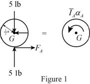
Here,
Refer to Figure 1.
Calculate the moment about point G by applying the equation of equilibrium:
Substitute
Show the free body diagram of the cylinder B as in Figure 2.
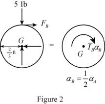
Here,
Refer to Figure 2.
Calculate the moment about point G by applying the equation of equilibrium:
Substitute
Show the free body diagram of the belt as in Figure 3.
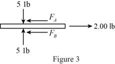
Refer to Figure 3.
Calculate the horizontal forces by applying the equation of equilibrium:
Sum of horizontal forces is equal to 0.
Calculate the angular acceleration of the cylinder A
Substitute
Calculate the horizontal force of the cylinder A
Substitute
Calculate the horizontal force of the cylinder B
Substitute
Calculate the magnitude of the friction force
Substitute
The horizontal forces of the cylinder A and B are greater than the magnitude of the friction force
Therefore, there is no slipping occurs between cylinders and belt.
(b)
Find the angular acceleration of each cylinder
(b)
Answer to Problem 16.40P
The angular acceleration of each cylinder
Explanation of Solution
The force pulled between cylinders A and B (P) is
The weight of the cylinder A
The weight of the cylinder B
The coefficient of the static friction
The coefficient of the kinetic friction
The radius of the cylinder A
The radius of the cylinder B
Calculation:
Refer the part (a).
Consider the no slipping occur at cylinder B.
Therefore, the angular acceleration of the cylinder B is
Calculate the angular acceleration of the cylinder A
Substitute
Calculate the angular acceleration of the cylinder B
Substitute
Hence, the angular acceleration of each cylinder
Want to see more full solutions like this?
Chapter 16 Solutions
Vector Mechanics for Engineers: Statics and Dynamics


- MY ID#016948724 please solve the problem step by spetarrow_forward1 8 4 For the table with 4×4 rows and columns as shown Add numbers so that the sum of any row or column equals .30 Use only these numbers: .1.2.3.4.5.6.10.11.12.12.13.14.14arrow_forwardMY ID# 016948724 please solve this problem step by steparrow_forward
- The pickup truck weighs 3220 Ib and reaches a speed of 30 mi/hr from rest in a distance of 200 ft up the 10-percent incline with constant acceleration. Calculate the normal force under each pair of wheels and the friction force under the rear driving wheels. The effective coefficient of friction between the tires and the road is known to be at least 0.8.arrow_forward1. The figure shows a car jack to support 400kg (W=400kg). In the drawing, the angle (0) varies between 15 and 70 °. The links are machined from AISI 1020 hot-rolled steel bars with a minimum yield strength of 380MPa. Each link consists of two bars, one on each side of the central bearings. The bars are 300mm in length (/) and 25 mm in width (w). The pinned ends have the buckling constant (C) of 1.4 for out of plane buckling. The design factor (nd) is 2.5. (1) Find the thickness (t) of the bars and the factor of safety (n). (2) Check if the bar is an Euler beam. Darrow_forward(Read image)arrow_forward
- UNIVERSIDAD NACIONAL DE SAN ANTONIO ABAD DEL CUSCO PRIMER EXAMEN PARCIAL DE MECÁNICA DE FLUIDOS I ............ Cusco, 23 de setiembre de 2024 AP. Y NOMBRES: ........ 1.- Para el tanque de la figura: a) Calcule la profundidad de la hidrolina si la profundidad del agua es de 2.8 m y el medidor del fondo del tanque da una lectura de 52.3kPa. b) Calcule la profundidad del agua si la profundidad de la hidrolina es 6.90 m y el medidor de la parte inferior del tanque registra una lectura de 125.3 kPa. Hidrolina Sp=0.90 Abertura Agua sup suge to but amulor quit y 2.- Calcule la magnitud de la fuerza resultante sobre el área A-B y la ubicación del centro de presión. Señale la fuerza resultante sobre el área y dimensione su ubicación con claridad. 3.5 ft 12 in: Oil (38-0.93) 14 in 8 inarrow_forwardplease solve this problem and give me the correct answer step by steparrow_forwardplease solve this problem step by step and show the best way that can be explainedarrow_forward
 International Edition---engineering Mechanics: St...Mechanical EngineeringISBN:9781305501607Author:Andrew Pytel And Jaan KiusalaasPublisher:CENGAGE L