
Concept explainers
Videos
(a)
Find the couple M.
(a)
Answer to Problem 16.136P
The couple M is
Explanation of Solution
Given information:
The mass of the rod BC is
The mass of the disk is
The mass of the rod CD is
The angular velocity is
The angular acceleration is
Calculation:
Consider the acceleration due to gravity as
Calculate the velocity of disk AB
Substitute
Calculate the velocity of rod BC
The velocity of disk AB is equal to the velocity of rod BC.
Substitute
Calculate the angular velocity of rod CD
Substitute
Apply the acceleration analysis as shown below.
Calculate the acceleration for disk AB
Substitute
Calculate the acceleration for rod BC
Substitute
Calculate the acceleration for rod CD
Substitute
Equating the components of Equations (1) and (2) as shown below.
Along x component.
Along y component.
Substitute
Calculate the acceleration of the mass centers as shown below.
Calculate the acceleration of mass center for disk AB
Calculate the acceleration of the mass center at P for rod BC
Substitute
Substitute
Calculate the acceleration of the mass center at Q for rod CD
Substitute
Calculate the inertial terms at mass centers as shown below.
The inertia terms at centers are
For disk AB.
For rod BC.
Substitute
For rod CD.
Substitute
Calculate the mass moment of inertia
For disk AB.
Substitute
For rod BC.
Substitute
For rod CD.
Substitute
Calculate the effective couples at mass centers as shown below.
The inertia terms at centers are
For disk AB.
For rod BC.
Substitute
For rod CD.
Substitute
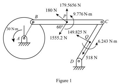
Sketch the effective force and couples on the system as shown in Figure 1.
Sketch the Free Body Diagram of the rod BC as shown in Figure 2.
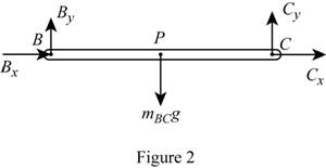
Refer to Figure 2.
Apply the Equilibrium of moment about B as shown below.
Substitute
Sketch the Free Body Diagram of the rod CD as shown in Figure 3.
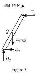
Refer to Figure 3.
Apply the Equilibrium of moment about D as shown below.
Substitute
Sketch the Free Body Diagram of the rod AB and BC as shown in Figure 4.
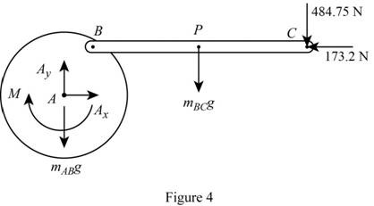
Refer to Figure 4.
Apply the Equilibrium of moment about A as shown below.
Substitute
Therefore, the couple M is
(b)
The components of force exerted at C on rod BC.
(b)
Answer to Problem 16.136P
The components of force exerted at C on rod BC is
Explanation of Solution
Given information:
The mass of the rod BC is
The mass of the disk is
The mass of the rod CD is
The angular velocity is
The angular acceleration is
Calculation:
Refer to part (a).
The components of force exerted at C on rod BC along x direction is
The components of force exerted at C on rod BC along y direction is
Therefore, the components of force exerted at C on rod BC is
Want to see more full solutions like this?
Chapter 16 Solutions
Vector Mechanics for Engineers: Statics and Dynamics


- (read image) (answer given)arrow_forwardA cylinder and a disk are used as pulleys, as shown in the figure. Using the data given in the figure, if a body of mass m = 3 kg is released from rest after falling a height h 1.5 m, find: a) The velocity of the body. b) The angular velocity of the disk. c) The number of revolutions the cylinder has made. T₁ F Rd = 0.2 m md = 2 kg T T₂1 Rc = 0.4 m mc = 5 kg ☐ m = 3 kgarrow_forward(read image) (answer given)arrow_forward
- 11-5. Compute all the dimensional changes for the steel bar when subjected to the loads shown. The proportional limit of the steel is 230 MPa. 265 kN 100 mm 600 kN 25 mm thickness X Z 600 kN 450 mm E=207×103 MPa; μ= 0.25 265 kNarrow_forwardT₁ F Rd = 0.2 m md = 2 kg T₂ Tz1 Rc = 0.4 m mc = 5 kg m = 3 kgarrow_forward2. Find a basis of solutions by the Frobenius method. Try to identify the series as expansions of known functions. (x + 2)²y" + (x + 2)y' - y = 0 ; Hint: Let: z = x+2arrow_forward
- 1. Find a power series solution in powers of x. y" - y' + x²y = 0arrow_forward3. Find a basis of solutions by the Frobenius method. Try to identify the series as expansions of known functions. 8x2y" +10xy' + (x 1)y = 0 -arrow_forwardHello I was going over the solution for this probem and I'm a bit confused on the last part. Can you please explain to me 1^4 was used for the Co of the tubular cross section? Thank you!arrow_forward
- Blood (HD = 0.45 in large diameter tubes) is forced through hollow fiber tubes that are 20 µm in diameter.Equating the volumetric flowrate expressions from (1) assuming marginal zone theory and (2) using an apparentviscosity for the blood, estimate the marginal zone thickness at this diameter. The viscosity of plasma is 1.2 cParrow_forwardQ2: Find the shear load on bolt A for the connection shown in Figure 2. Dimensions are in mm Fig. 2 24 0-0 0-0 A 180kN (10 Markarrow_forwarddetermine the direction and magnitude of angular velocity ω3 of link CD in the four-bar linkage using the relative velocity graphical methodarrow_forward
 Elements Of ElectromagneticsMechanical EngineeringISBN:9780190698614Author:Sadiku, Matthew N. O.Publisher:Oxford University Press
 Mechanics of Materials (10th Edition)Mechanical EngineeringISBN:9780134319650Author:Russell C. HibbelerPublisher:PEARSON
 Thermodynamics: An Engineering ApproachMechanical EngineeringISBN:9781259822674Author:Yunus A. Cengel Dr., Michael A. BolesPublisher:McGraw-Hill Education
 Control Systems EngineeringMechanical EngineeringISBN:9781118170519Author:Norman S. NisePublisher:WILEY
 Mechanics of Materials (MindTap Course List)Mechanical EngineeringISBN:9781337093347Author:Barry J. Goodno, James M. GerePublisher:Cengage Learning
 Engineering Mechanics: StaticsMechanical EngineeringISBN:9781118807330Author:James L. Meriam, L. G. Kraige, J. N. BoltonPublisher:WILEY