Concept explainers
Videos
yB so that the ball will enter the basket.
Answer to Problem 13.77P
The value of yB=0.488m.
Explanation of Solution
Consider the diagram of the suspended ball by an inextensible cord.
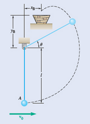
Let us consider at point “A” as position 1 and then the point described by the angle is considered as position 2.
The path of the ball changes from the circular motion to parabolic motion.
So far then the tension in the cord becomes zero.

From the above diagram x-coordinate of the ball at the position 2 is taken as x2.
Then the y-coordinate of the ball at position 2 is takes as y2.
So the free body diagram of the ball at position 2 is calculated by :
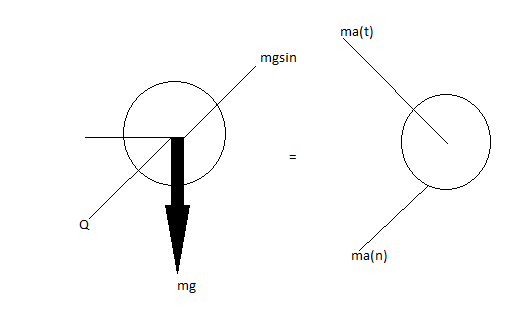
Then apply the newton’s second law after that resolve the forces acting on the ball at the position 2
So, here the cord becomes slack at point 2.
And substitute Q=0 in above formula, we get the:
Here applying the conservation of energy at position 1 and 2 for the ball.
To find the angle swept by the ball is
Then formulate the kinetic energy of the ball at position 1 as T1.
Formulate the potential energy of the ball, we get:
Here we have to substitute h=l, we get:
Formulate the kinetic energy of the ball at the position 2 to be considered as T2.
Formulate the potential energy of the ball at point 2 is V2.
Consider equation 1 and substitute required values.
Substitute
Finally from equation (1) we get:
Substitute required values, we get:
Then, find the velocity of the ball at point 2.
After that the velocity of the projectile ball after reaches its point 2 is to be vp.
In this we have horizontal velocity component and vertical velocity component.
Formulate the horizontal velocity component of the projectile ball along with −ve X-axis.
Formulate the horizontal distance between the basket and point of suspension of the ball.
Substitute
Formulate the vertical velocity component of the projectile ball with the negative X-axis.
Vertical distance between the basket and the point of suspension is to be yB..
Substitute
Find the y-coordinate value by substituting all the required values.
Want to see more full solutions like this?
Chapter 13 Solutions
Vector Mechanics for Engineers: Dynamics


- 1 8 4 Add numbers so that the sum of any row or column equals .30 Use only these numbers: .1.2.3.4.5.6.10.11.12.12.13.14.14arrow_forwardUppgift 2 (9p) I77777 20 kN 10 kN/m 4 [m] 2 2 Bestäm tvärkrafts- och momentdiagram för balken i figuren ovan. Extrempunkter ska anges med både läge och värde i diagrammen.arrow_forward**Problem 8-45.** The man has a mass of 60 kg and the crate has a mass of 100 kg. If the coefficient of static friction between his shoes and the ground is \( \mu_s = 0.4 \) and between the crate and the ground is \( \mu_c = 0.3 \), determine if the man is able to move the crate using the rope-and-pulley system shown. **Diagram Explanation:** The diagram illustrates a scenario where a man is attempting to pull a crate using a rope-and-pulley system. The setup is as follows: - **Crate (C):** Positioned on the ground with a rope attached. - **Rope:** Connects the crate to a pulley system and extends to the man. - **Pulley on Tree:** The rope runs over a pulley mounted on a tree which redirects the rope. - **Angles:** - The rope between the crate and tree forms a \(30^\circ\) angle with the horizontal. - The rope between the tree and the man makes a \(45^\circ\) angle with the horizontal. - **Man (A):** Pulling on the rope with the intention of moving the crate. This arrangement tests the…arrow_forward
- please solve this problems follow what the question are asking to do please show me step by steparrow_forwardplease first write the line action find the forces and them solve the problem step by steparrow_forwardplease solve this problem what the problem are asking to solve please explain step by step and give me the correct answerarrow_forward
- please help me to solve this problem step by steparrow_forwardplease help me to solve this problem and determine the stress for each point i like to be explained step by step with the correct answerarrow_forwardplease solve this problem for me the best way that you can explained to solve please show me the step how to solvearrow_forward
 Elements Of ElectromagneticsMechanical EngineeringISBN:9780190698614Author:Sadiku, Matthew N. O.Publisher:Oxford University Press
 Mechanics of Materials (10th Edition)Mechanical EngineeringISBN:9780134319650Author:Russell C. HibbelerPublisher:PEARSON
 Thermodynamics: An Engineering ApproachMechanical EngineeringISBN:9781259822674Author:Yunus A. Cengel Dr., Michael A. BolesPublisher:McGraw-Hill Education
 Control Systems EngineeringMechanical EngineeringISBN:9781118170519Author:Norman S. NisePublisher:WILEY
 Mechanics of Materials (MindTap Course List)Mechanical EngineeringISBN:9781337093347Author:Barry J. Goodno, James M. GerePublisher:Cengage Learning
 Engineering Mechanics: StaticsMechanical EngineeringISBN:9781118807330Author:James L. Meriam, L. G. Kraige, J. N. BoltonPublisher:WILEY