
Videos
Using Fig. 9.43, design a problem to help other students better understand impedance.
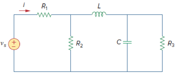
Figure 9.43
Design a problem to make better understand about the impedance using Figure 9.43.
Explanation of Solution
Problem design:
Determine the value of current
Formula used:
Write the expression to convert the time domain expression into phasor domain.
Here,
A is the magnitude,
t is the time, and
Write the expression to calculate the phasor current.
Here,
Write the expression to calculate the impedance of the passive elements resistor, inductor and capacitor.
Here,
Calculation:
The Figure 9.43 is redrawn as Figure 1 by assuming the values for the passive elements.
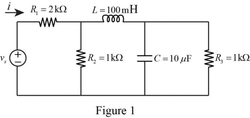
Given voltage equation is,
Here, angular frequency
Use the equation (1) to express the above equation in phasor form.
Substitute
Substitute
Substitute
Substitute
Substitute
The Figure 1 is redrawn as impedance circuit in the following Figure 2.
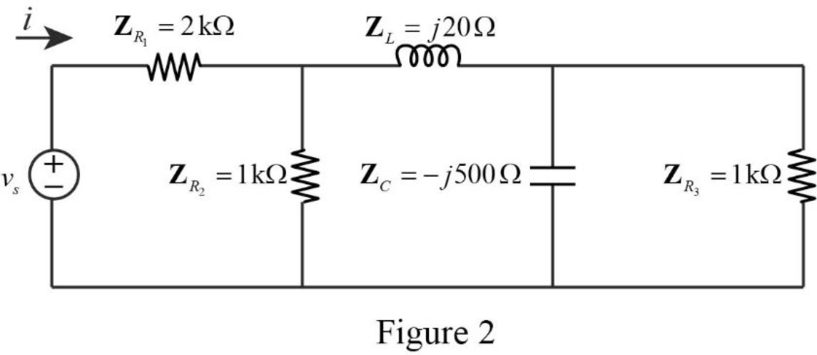
Refer to Figure 2, the impedances
Write the expression to calculate the equivalent capacitance 1 for the parallel connected impedances
Here,
Substitute
The reduced circuit of the Figure 2 is drawn as Figure 3.
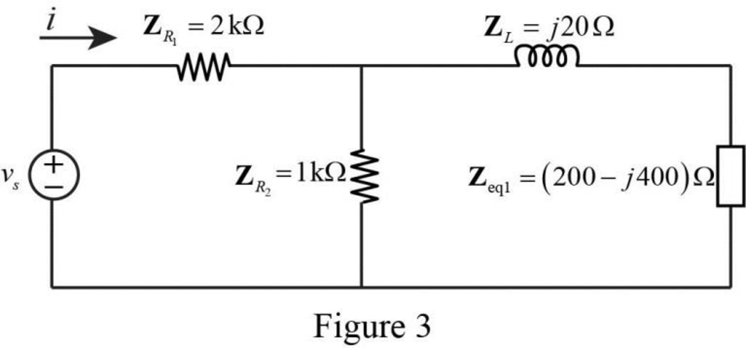
Refer to Figure 3, the impedances
Write the expression to calculate the equivalent capacitance 2 for the series connected impedances
Here,
Substitute
The reduced circuit of the Figure 3 is drawn as Figure 4.
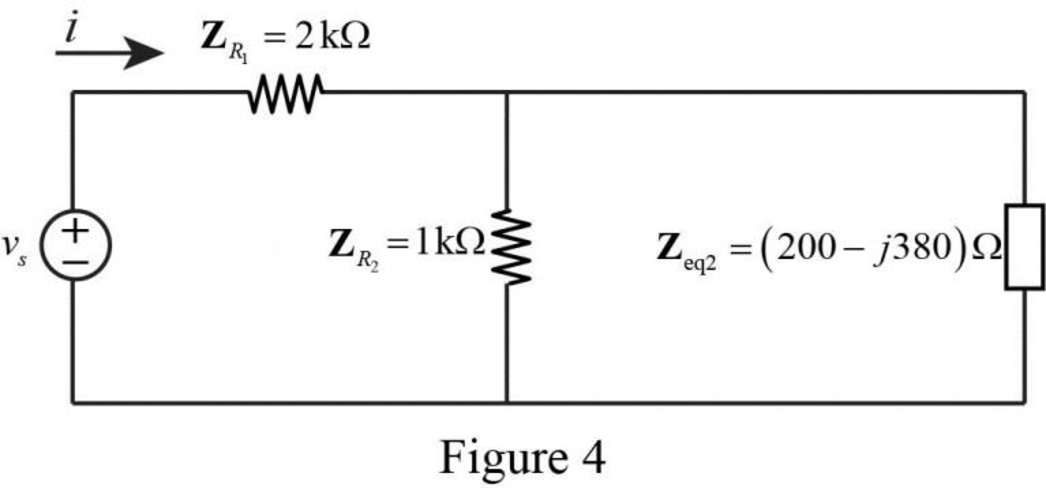
Refer to Figure 4, the impedances
Write the expression to calculate the equivalent capacitance 3 for the parallel connected impedances
Here,
Substitute
The reduced circuit of the Figure 4 is drawn as Figure 5.
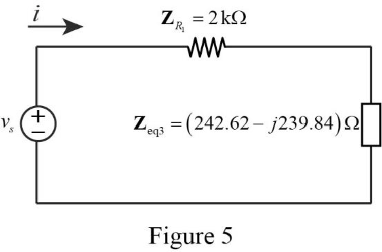
Refer to Figure 5, the impedances
Write the expression to calculate the equivalent capacitance 4 for the series connected impedances
Here,
Substitute
The reduced circuit of the Figure 5 is drawn as Figure 6.
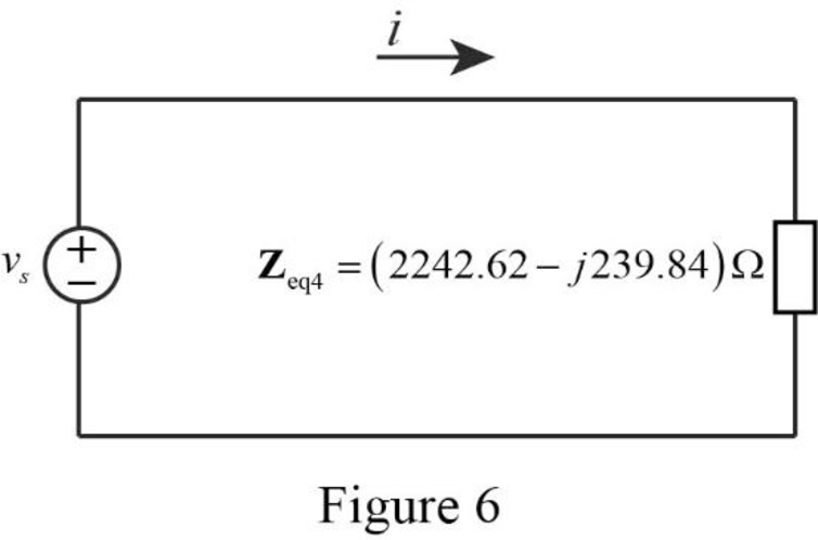
Therefore, the equivalent impedance of the circuit in Figure 1 is,
Substitute
Use the equation (1) to express the above equation in time domain form.
Substitute
Therefore, the value of current
Conclusion:
Thus, the problem to make better understand about the impedance using Figure 9.43 is designed.
Want to see more full solutions like this?
Chapter 9 Solutions
Fundamentals of Electric Circuits
Additional Engineering Textbook Solutions
Electric Circuits. (11th Edition)
Database Concepts (8th Edition)
Starting Out with C++: Early Objects (9th Edition)
Starting Out with Java: From Control Structures through Data Structures (4th Edition) (What's New in Computer Science)
Modern Database Management
Management Information Systems: Managing The Digital Firm (16th Edition)


- A conductor 300 mm long carries a current of 13A and is at right-angles to a magnetic fieldbetween two circular pole faces, each of diameter 80 mm. If the total flux between the polefaces is 0.75 mWb, calculate the force exerted on the conductor. [ANS = 0.582 N]arrow_forwarda) find Rthb) Find Vth in the circuit c)Draw the Thevenin Equivalent of the circuit to tge left of the a and b terminalsarrow_forwardAn electric car runs on batteries, but needs to make constant stops to re-charge. If a trailer is attached to the car that carries a generator, and the generator is turned by a belt attached to the wheels of the trailer, will the car be able to drive forever without stopping?arrow_forward
- A singl core cable of voltage 30 kv. The diameter of Conductor is 3 cm. The diameter of cable is 25 cm. This cable has Two layer of insulator having arelative permittivity 5-3 respectively of The ratio of maximum electric stress of maximum electric stress 8 First layer to the of second layer is 10 Find & 1- The thickness of each layers. 3- The voltage of each layers. §. Layers The saving in radius of cable if another ungrading cable has the Same maximum electric stress, Total village, Conductor diameter of grading cable.arrow_forward66 KV sing care Cable has a drameter of conductor of 3 cm. The radius of cable is 10 cm. This Cable house Two relative permmitivity of insulation 6 and 4 respectively. If The ratio of maximum electric stress of first layer to the maximum eledric streep & second layer is s 1- find the village & each layers. 2- Min- electric stress J Cable 3- Compare the voltage of ungrading Cable has the same distance and relectric stresses.arrow_forwardPrelab Information 1. Laboratory Preliminary Discussion First-order Low-pass RC Filter Analysis The first-order low-pass RC filter shown in figure 1 below represents all voltages and currents in the time domain. It is of course possible to solve for all circuit voltages using time domain differential equation techniques, but it is more efficient to convert the circuit to its s-domain equivalent as shown in figure 2 and apply Laplace transform techniques. vs(t) i₁(t) + R₁ ww V₁(t) 12(t) Lic(t) Vout(t) = V2(t) R₂ Vc(t) C Vc(t) VR2(t) = V2(t) + Vs(s) Figure 1: A first-order low-pass RC filter represented in the time domain. I₁(s) R1 W + V₁(s) V₂(s) 12(s) Ic(s) + Vout(S) == Vc(s) Vc(s) Zc(s) = = VR2(S) V2(s) Figure 2: A first-order low-pass RC filter represented in the s-domain.arrow_forward
- Solve it in a different way than the previous solution that I searched forarrow_forwardA lossless uncharged transmission line of length L = 0.45 cm has a characteristic impedance of 60 ohms. It is driven by an ideal voltage generator producing a pulse of amplitude 10V and width 2 nS. If the transmission line is connected to a load of 200 ohms, sketch the voltage at the load as a function of time for the interval 0 < t < 20 nS. You may assume that the propagation velocity of the transmission is c/2. Answered now answer number 2. Repeat Q.1 but now assume the width of the pulse produced by the generator is 4 nS. Sketch the voltage at the load as a function of time for 0 < t < 20 nS.arrow_forwardSolve this experiment with an accurate solution, please. Thank you.arrow_forward
 Introductory Circuit Analysis (13th Edition)Electrical EngineeringISBN:9780133923605Author:Robert L. BoylestadPublisher:PEARSON
 Delmar's Standard Textbook Of ElectricityElectrical EngineeringISBN:9781337900348Author:Stephen L. HermanPublisher:Cengage Learning
 Programmable Logic ControllersElectrical EngineeringISBN:9780073373843Author:Frank D. PetruzellaPublisher:McGraw-Hill Education
 Fundamentals of Electric CircuitsElectrical EngineeringISBN:9780078028229Author:Charles K Alexander, Matthew SadikuPublisher:McGraw-Hill Education
 Electric Circuits. (11th Edition)Electrical EngineeringISBN:9780134746968Author:James W. Nilsson, Susan RiedelPublisher:PEARSON
 Engineering ElectromagneticsElectrical EngineeringISBN:9780078028151Author:Hayt, William H. (william Hart), Jr, BUCK, John A.Publisher:Mcgraw-hill Education,