
Fundamentals of Electric Circuits
6th Edition
ISBN: 9780078028229
Author: Charles K Alexander, Matthew Sadiku
Publisher: McGraw-Hill Education
expand_more
expand_more
format_list_bulleted
Videos
Textbook Question
Chapter 9, Problem 61P
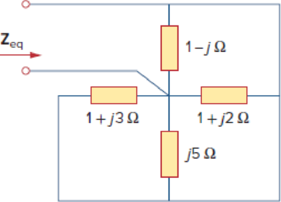
Find Zeq in the circuit in Fig. 9.68.
Figure 9.68
Expert Solution & Answer
Want to see the full answer?
Check out a sample textbook solution
Students have asked these similar questions
This exam is closed book, but you may use one 8.5x11" sheet of notes (both sides), handwritten by you
Wote all answers
kot on this test paper! Use the personal key number N (written above)
on the parameters se fix
to
Show your work and explain your reasoning Partial credit will be given for partial solutions. When giving
a numerical answer, specify units ill any apply. No credit will be given for solving problems from previous
1. For the AM signal with periodic message m()
shown in Fig. 1 and modulation index
= 0.03A
a) find the carrier amplitude and carrier power;
b) find the sideband power and compute the power
efficiency &
N = 15
4+N
AA
-(4+N)
Fig. 1
r(s)→
1. Tests of a 10 kVA, 230/2300 V single-phase transformer have yielded the following results:
Vacuum test low voltage side: current = 0.45A Po = 70WLow side short circuit test: voltage = 11.6V Pcc = 224.3WDetermine:
a. Parameters Rcc and Xcc of the equivalent circuit referring to the secondary.b. Transformer voltage regulation, if feeding a load of 4kVA, fp = 0.75 in delayc. Efficiency if the load is 7kVA, fp = 0.8 inductiveperform the calculations without using artificial intelligence, let it be by one of the assigned people please
=
5. Design an Armstrong indirect FM modulator that generates an FM signal with a carrier frequency of
(60+2M) MHz and Af 30 kHz. Use a narrowband FM generator with f. 200 kHz and Af= 12 Hz. The
local oscillator must operate at a frequency in the range of 5-8 MHz, and frequency doublers, triplers, and
quintuplers are available. Sketch the block diagram of your design, including values of all relevant
parameters.
Chapter 9 Solutions
Fundamentals of Electric Circuits
Ch. 9.2 - Practice Problem 9.1 Given the sinusoid 45 cos(5t...Ch. 9.2 - Practice Problem 9.2 Find the phase angle between...Ch. 9.3 - Prob. 3PPCh. 9.3 - Express these sinusoids as phasors: (a)...Ch. 9.3 - Find the sinusoids corresponding to these phasors:...Ch. 9.3 - If v1=10sint30V and v2=20cost+45V, find v=v1+v2.Ch. 9.3 - Prob. 7PPCh. 9.4 - If voltage v=25sin100t15V is applied to a 50F...Ch. 9.5 - Refer to Fig. 9.17. Determine v(t) and i(t).Ch. 9.7 - Determine the input impedance of the circuit in...
Ch. 9.7 - Calculate vo in the circuit of Fig. 9.27. Figure...Ch. 9.7 - Find I in the circuit of Fig. 9.30. Figure 9.30Ch. 9.8 - Design an RC circuit to provide a 90 lagging phase...Ch. 9.8 - Refer to the RL circuit in Fig. 9.36. If 10 V is...Ch. 9.8 - In the ac bridge circuit of Fig. 9.37, suppose...Ch. 9 - Which of the following is not a right way to...Ch. 9 - A function that repeats itself after fixed...Ch. 9 - Which of these frequencies has the shorter period?...Ch. 9 - If v1 = 30 sin(t + 10) and v2 = 20 sin(t + 50),...Ch. 9 - The voltage across an inductor leads the current...Ch. 9 - The imaginary part of impedance is called:...Ch. 9 - The impedance of a capacitor increases with...Ch. 9 - At what frequency will the output voltage v0(t) in...Ch. 9 - A series RC circuit has VR = 12 V and VC = 5 V....Ch. 9 - A series RCL circuit has R = 30 , XC = 50 , and XL...Ch. 9 - Given the sinusoidal voltage v(t) = 50 cos (30t +...Ch. 9 - A current source in a linear circuit has...Ch. 9 - Express the following functions in cosine form:...Ch. 9 - Design a problem to help other students better...Ch. 9 - Given v1=45sint+30V and v2=50cost30V, determine...Ch. 9 - For the following pairs of sinusoids, determine...Ch. 9 - If f() = cos + j sin , show that f() = ej.Ch. 9 - Calculate these complex numbers and express your...Ch. 9 - Evaluate the following complex numbers and leave...Ch. 9 - Design a problem to help other students better...Ch. 9 - Find the phasors corresponding to the following...Ch. 9 - Let X=440 and Y=2030. Evaluate the following...Ch. 9 - Evaluate the following complex numbers: (a)...Ch. 9 - Simplify the following expression: (a)...Ch. 9 - Evaluate these determinants: (a) 10+j62j351+j (b)...Ch. 9 - Prob. 16PCh. 9 - Two voltages v1 and v2 appear in series so that...Ch. 9 - Obtain the sinusoids corresponding to each of the...Ch. 9 - Using phasors, find: (a) 3cos20t+105cos20t30 (b)...Ch. 9 - A linear network has a current input 7.5cos10t+30A...Ch. 9 - Simplify the following: (a) ft=5cos2t+154sin2t30...Ch. 9 - An alternating voltage is given by v(t) = 55...Ch. 9 - Apply phasor analysis to evaluate the following:...Ch. 9 - Find v(t) in the following integrodifferential...Ch. 9 - Using phasors, determine i(t) in the following...Ch. 9 - Prob. 26PCh. 9 - A parallel RLC circuit has the node equation...Ch. 9 - Determine the current that flows through an 20-...Ch. 9 - Given that vc(0) = 2 cos(155) V, what is the...Ch. 9 - A voltage v(t) = 100 cos(60t + 20) V is applied to...Ch. 9 - A series RLC circuit has R = 80 , L = 240 mH, and...Ch. 9 - Using Fig. 9.40, design a problem to help other...Ch. 9 - A series RL circuit is connected to a 220-V ac...Ch. 9 - What value of will cause the forced response, vo...Ch. 9 - Find the steady-state current i in the circuit of...Ch. 9 - Using Fig. 9.43, design a problem to help other...Ch. 9 - Determine the admittance Y for the circuit in Fig....Ch. 9 - Using Fig. 9.45, design a problem to help other...Ch. 9 - For the circuit shown in Fig. 9.46, find Zeq and...Ch. 9 - In the circuit of Fig. 9.47, find io when: (a) =...Ch. 9 - Find v(t) in the RLC circuit of Fig. 9.48. Figure...Ch. 9 - Calculate vo(t) in the circuit of Fig. 9.49....Ch. 9 - Find current Io in the circuit shown in Fig. 9.50....Ch. 9 - Calculate i(t) in the circuit of Fig. 9.51. Figure...Ch. 9 - Find current Io in the network of Fig. 9.52....Ch. 9 - If vs = 100 sin(10t + 18) V in the circuit of Fig....Ch. 9 - In the circuit of Fig. 9.54, determine the value...Ch. 9 - Given that vs(t) = 20 sin (100t 40) in Fig. 9.55,...Ch. 9 - Find vs (t) in the circuit of Fig. 9.56 if the...Ch. 9 - Determine vx in the circuit of Fig. 9.57. Let...Ch. 9 - If the voltage vo across the 2- resistor in the...Ch. 9 - If V in the circuit of Fig. 9.59, find Is. Figure...Ch. 9 - Find Io in the circuit of Fig. 9.60.Ch. 9 - In the circuit of Fig. 9.61, Find Vs if Io=300A.Ch. 9 - Find Z in the network of Fig. 9.62, given that...Ch. 9 - At = 377 rad/s, find the input impedance of the...Ch. 9 - At = 1 rad/s, obtain the input admittance in the...Ch. 9 - Using Fig. 9.65, design a problem to help other...Ch. 9 - For the network in Fig. 9.66, find Zin. Let = 100...Ch. 9 - Obtain Zin for the circuit in Fig. 9.67. Figure...Ch. 9 - Find Zeq in the circuit in Fig. 9.68. Figure 9.68Ch. 9 - For the circuit in Fig. 9.69, find the input...Ch. 9 - For the circuit in Fig. 9.70, find the value of...Ch. 9 - Find ZT and Vo in the circuit in Fig. 9.71. Let...Ch. 9 - Determine ZT and I for the circuit in Fig. 9.72....Ch. 9 - For the circuit in Fig. 9.73, calculate ZT and...Ch. 9 - At = 103 rad/s, find the input admittance of each...Ch. 9 - Determine Yeq for the circuit in Fig. 9.75. Figure...Ch. 9 - Find the equivalent admittance Yeq of the circuit...Ch. 9 - Find the equivalent impedance of the circuit in...Ch. 9 - Obtain the equivalent impedance of the circuit in...Ch. 9 - Calculate the value of Zab in the network of Fig....Ch. 9 - Determine the equivalent impedance of the circuit...Ch. 9 - Design an RL circuit to provide a 90 leading phase...Ch. 9 - Design a circuit that will transform a sinusoidal...Ch. 9 - For the following pairs of signals, determine if...Ch. 9 - Refer to the RC circuit in Fig. 9.81. (a)...Ch. 9 - A coil with impedance 8 + j6 is connected in...Ch. 9 - (a) Calculate the phase shift of the circuit in...Ch. 9 - Consider the phase-shifting circuit in Fig. 9.83....Ch. 9 - The ac bridge in Fig. 9.37 is balanced when R1 =...Ch. 9 - A capacitance bridge balances when R1 = 100 , R2 =...Ch. 9 - An inductive bridge balances when R1 = 1.2 k, R2 =...Ch. 9 - The ac bridge shown in Fig. 9.84 is known as a...Ch. 9 - The ac bridge circuit of Fig. 9.85 is called a...Ch. 9 - The circuit shown in Fig. 9.86 is used in a...Ch. 9 - The network in Fig. 9.87 is part of the schematic...Ch. 9 - A series audio circuit is shown in Fig. 9.88. (a)...Ch. 9 - An industrial load is modeled as a series...Ch. 9 - An industrial coil is modeled as a series...Ch. 9 - Figure 9.91 shows a series combination of an...Ch. 9 - A transmission line has a series impedance of and...Ch. 9 - A power transmission system is modeled as shown in...
Knowledge Booster


Learn more about
Need a deep-dive on the concept behind this application? Look no further. Learn more about this topic, electrical-engineering and related others by exploring similar questions and additional content below.Similar questions
- 4. The system shown below must recover both messages from the frequency-division multiplexed signal whose spectrum is input to it. a) Determine the frequency of the local oscillator; b) determine the bandwidths B, and B2 of the two low-pass filters; and c) sketch the spectra of the output signals, numbering key points on the frequency & amplitude axes. 艹 f(kHz) Wipw -12V 4 cos(27fLal) LPF1 MS) LPF2 MSarrow_forward3. In a QAM receiver using synchronous detection, the local oscillator produces an accurate cosine wave 2cos(x), but the two receiver branches have mismatched lengths, causing a phase delay of -1/(3+N) radians in one branch, as shown. Compute the component of the quadrature channel message appearing in the in-phase output, and compute the component of the in-phase message appearing in the quadrature output. QAM signal Low-pass filter 151(1) (1) 200001 #12 2 sin[)] Ap= Low-pass -л(3+N) filter x2(1) my(1)arrow_forward2. For the message signal m(r) shown below: -2 a) sketch the FM waveform pru if -2xx 10', k-100Nx. Specify the maximum instantaneous frequency and the minimum instantaneous frequency values in kHz. b) sketch the PM waveform pru if -2x10' and k,-/4. As well as the maximum and minimum instantaneous frequency, specify the value of the phase shift at key points. 5x10*N- ww N=15arrow_forward
- Don't use ai to answer I will report you answerarrow_forwardPlease describe how to do each step in detail. thanksarrow_forward2. For the OPAMP below: g) Grounding the inputs, perform a DC analysis (assume beta is infinite and VBE=0.7V and neglect the early voltage),calculate the DC currents and voltages everywhere in the circuit (all the collector and emitter currents and voltages aswell as the output voltage). Note that Q4 is 4 times as big as Q9 and Q3h) If Q1 and Q2 have a beta of 100, calculate the input bias current to the opampi) What is the input common mode range of this opamp?j) Calculate the common mode gain if the early voltage of Q3 and Q6 is 50Vk) Calculate the differential gain vo/vid of this circuitI) Calculate the input and output impedance of the opamp assuming beta is 100m) Calculate the input referred offset (Vos) if R2=21Karrow_forward
- 1. For the difference amplifier below, R1=R3=10K, R2=R4=50k, assume opamp is ideala) Find the differential mode gain, Admb) Find the input impedance (differential, between wi and va)c) Find the common mode gain in the presence of resistor mismatch (If R3=R1+ deltaR1, R4=R2+ deltaR2, deltaR1=100, deltaR2=500)d) Find the common mode rejection ratio (CMRR)e) Find the input impedance and output impedancef) If the OPAMP has an input current of 100uA, find the output offset voltage, set Vi1 = Vi2=0Varrow_forwardFor the circuit shown, I-20 mA, R₁ =10000 2, R2 =2000 Q, R3 -2000 Q, R₁-6000 2, Vcc 5 V and the OPAMP is ideal with regions of operation are considered. The output current lo in mA is (choose the closet value): R₂ Is R₁ W VCC -VCC The relative tolerance for this problem is 1 %. -0.458 -0.833 6.667 -6.667 ○ 0.458 0.833 w R3 w RLarrow_forwardFor the circuit shown, let R₁-4, R2-50, R3-2, R4-77 and Vin-18. Find the current I₁ and voltage Vo as follows: Use op-amp building blocks to determine the voltage Vo1: V01 = Then use Vo1 to find the current 11: 1₁ = Find the voltage Vo: Vo= R1 www Vin R₂ ww V01 R3 The relative tolerance for this problem is 9 %. + R4 www +5°arrow_forward
- For the circuit shown, let Vs1 = 13, Vs2 = 7 R1-10, R2= 50, assume ideal-op-amp, and find • The current Is • The output voltage Vo= VSI A S R₁ ww 1 R₂ www V₁₂ + Varrow_forwardFor the circuit shown, let R₁ =16 Q, R₂ =48 2, R3 = 28 2, R4 =84 02, R5 -2002, R6 -80 2, and V₁ =4 mV. Assume ideal op-amp, find (round your answer to three digits) : Va= (MV) Vb = (MV) (mA) Vout = (MV) R₁ R₂ V₁ + R3 Vb W The relative tolerance for this problem is 7 %. ww R4 24 R5 55 R6 VOUTarrow_forwardFor the circuit shown, find the voltage Vo and current l。. Let R₁=8, R2=1, R3-11 and V₂-3. V S (+1 || w R₂ R1 + R3 Vo The voltage Vo is: The current lo is: The relative tolerance for this problem is 3 %.arrow_forward
arrow_back_ios
SEE MORE QUESTIONS
arrow_forward_ios
Recommended textbooks for you
 Introductory Circuit Analysis (13th Edition)Electrical EngineeringISBN:9780133923605Author:Robert L. BoylestadPublisher:PEARSON
 Delmar's Standard Textbook Of ElectricityElectrical EngineeringISBN:9781337900348Author:Stephen L. HermanPublisher:Cengage Learning
 Programmable Logic ControllersElectrical EngineeringISBN:9780073373843Author:Frank D. PetruzellaPublisher:McGraw-Hill Education
 Fundamentals of Electric CircuitsElectrical EngineeringISBN:9780078028229Author:Charles K Alexander, Matthew SadikuPublisher:McGraw-Hill Education
 Electric Circuits. (11th Edition)Electrical EngineeringISBN:9780134746968Author:James W. Nilsson, Susan RiedelPublisher:PEARSON
 Engineering ElectromagneticsElectrical EngineeringISBN:9780078028151Author:Hayt, William H. (william Hart), Jr, BUCK, John A.Publisher:Mcgraw-hill Education,
Introductory Circuit Analysis (13th Edition)
Electrical Engineering
ISBN:9780133923605
Author:Robert L. Boylestad
Publisher:PEARSON
Delmar's Standard Textbook Of Electricity
Electrical Engineering
ISBN:9781337900348
Author:Stephen L. Herman
Publisher:Cengage Learning
Programmable Logic Controllers
Electrical Engineering
ISBN:9780073373843
Author:Frank D. Petruzella
Publisher:McGraw-Hill Education
Fundamentals of Electric Circuits
Electrical Engineering
ISBN:9780078028229
Author:Charles K Alexander, Matthew Sadiku
Publisher:McGraw-Hill Education
Electric Circuits. (11th Edition)
Electrical Engineering
ISBN:9780134746968
Author:James W. Nilsson, Susan Riedel
Publisher:PEARSON
Engineering Electromagnetics
Electrical Engineering
ISBN:9780078028151
Author:Hayt, William H. (william Hart), Jr, BUCK, John A.
Publisher:Mcgraw-hill Education,
Y Parameters - Admittance Parameters; Author: Electrical Engineering Authority;https://www.youtube.com/watch?v=MLqqa8YbVrA;License: Standard Youtube License