
Videos
Find v(t) in the RLC circuit of Fig. 9.48.
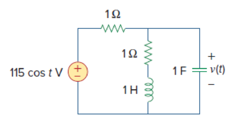
Figure 9.48
Find the value the voltage
Answer to Problem 41P
The value of the voltage
Explanation of Solution
Given date:
Refer to Figure 9.48 in the textbook.
Formula used:
Write the expression to convert the time domain expression into phasor domain.
Here,
A is the magnitude,
t is the time, and
Write the expression to calculate the total phasor current.
Here,
Write the expression to calculate the impedance of the passive elements resistor, inductor and capacitor.
Here,
Calculation:
The given RLC circuit is redrawn as Figure 1.
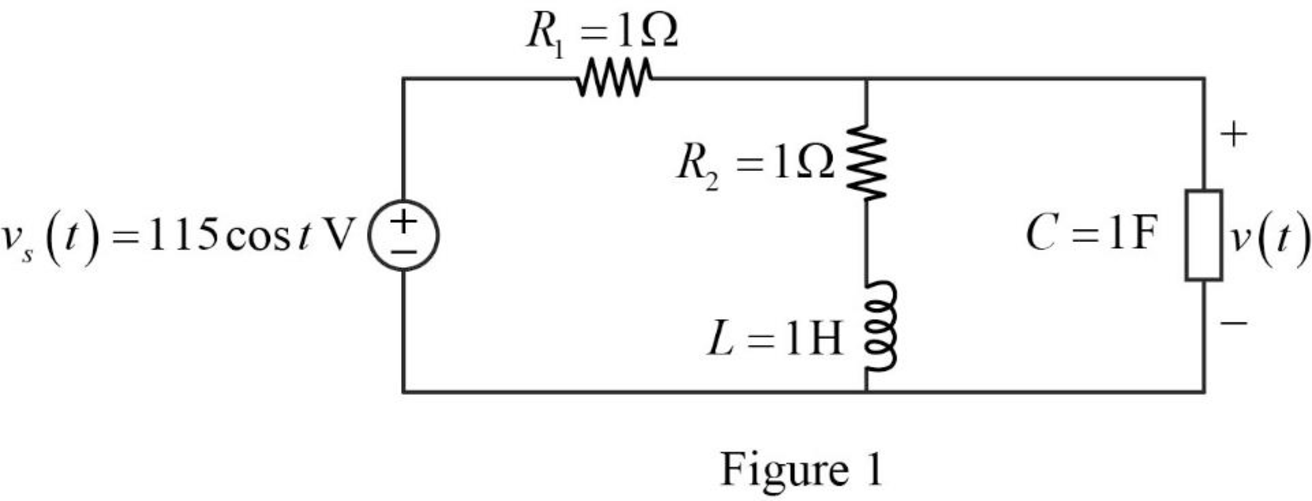
Refer to Figure 1, the source voltage is,
Here, angular frequency
Use the equation (1) to express the above equation in phasor form.
Substitute
Substitute
Substitute
Substitute
The Figure 1 is redrawn as impedance circuit in the following Figure 2.
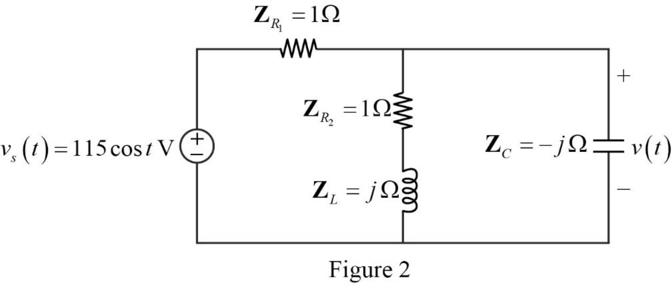
Refer to Figure 2, the series combination of the impedances
Write the expression to calculate the equivalent impedance 1 for the parallel combination as follows.
Here,
Substitute
The reduced circuit of the Figure 2 is drawn as Figure 3.
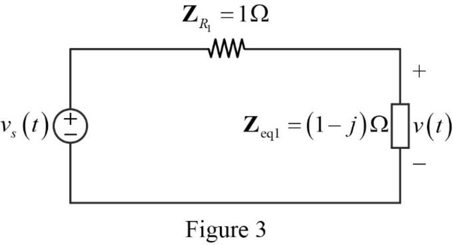
Refer to Figure 2, the impedances
Write the expression to calculate the equivalent capacitance for the series connected impedances
Here,
Substitute
The reduced circuit of the Figure 3 is drawn as Figure 4.
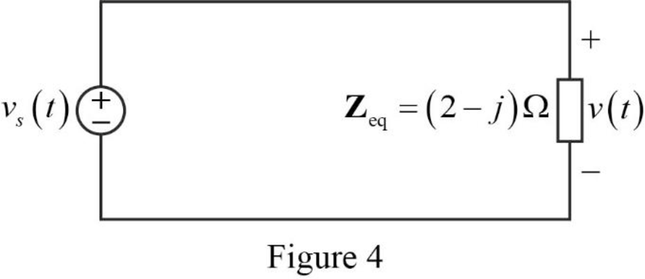
Substitute
Refer to Figure 2, the current through the capacitor is expressed as,
Refer to Figure 2, the voltage across the capacitor is expressed as,
Substitute
Substitute
Use the equation (1) to express the above equation in time domain form.
Substitute
Conclusion:
Thus, the value of the voltage
Want to see more full solutions like this?
Chapter 9 Solutions
Fundamentals of Electric Circuits
Additional Engineering Textbook Solutions
Starting Out with Python (4th Edition)
Elementary Surveying: An Introduction To Geomatics (15th Edition)
Starting Out with Programming Logic and Design (5th Edition) (What's New in Computer Science)
Java: An Introduction to Problem Solving and Programming (8th Edition)
Automotive Technology: Principles, Diagnosis, And Service (6th Edition) (halderman Automotive Series)
Thinking Like an Engineer: An Active Learning Approach (4th Edition)


- For the circuit shown, let R₁-4, R2-50, R3-2, R4-77 and Vin-18. Find the current I₁ and voltage Vo as follows: Use op-amp building blocks to determine the voltage Vo1: V01 = Then use Vo1 to find the current 11: 1₁ = Find the voltage Vo: Vo= R1 www Vin R₂ ww V01 R3 The relative tolerance for this problem is 9 %. + R4 www +5°arrow_forwardFor the circuit shown, let Vs1 = 13, Vs2 = 7 R1-10, R2= 50, assume ideal-op-amp, and find • The current Is • The output voltage Vo= VSI A S R₁ ww 1 R₂ www V₁₂ + Varrow_forwardFor the circuit shown, let R₁ =16 Q, R₂ =48 2, R3 = 28 2, R4 =84 02, R5 -2002, R6 -80 2, and V₁ =4 mV. Assume ideal op-amp, find (round your answer to three digits) : Va= (MV) Vb = (MV) (mA) Vout = (MV) R₁ R₂ V₁ + R3 Vb W The relative tolerance for this problem is 7 %. ww R4 24 R5 55 R6 VOUTarrow_forward
- For the circuit shown, find the voltage Vo and current l。. Let R₁=8, R2=1, R3-11 and V₂-3. V S (+1 || w R₂ R1 + R3 Vo The voltage Vo is: The current lo is: The relative tolerance for this problem is 3 %.arrow_forwardFor the circuit shown, find currents 11, 12, 13, and the voltage Vo. Assume ideal op-amp, and let R₁=3, R2-40, Ro=85 and 1-6 The current I₁ is: The current 12 is: The current 13 is: The voltage Vo is: R₂ w R₁ 13 w Roarrow_forwardFor the circuit shown, let v₂ = 9, R₁=86, R2= 15, R3 =7, assume ideal-op-amp, and find • The current l₂ = • Voltage gain, Av= Vo/Vs= • The output voltage vo = A US 1+ 1. R₁ R₂ R3 10 +arrow_forward
- For the op-amp circuit shown, find the voltage Vo, and the current lo. Let R₁=8, R2=58, R3-27 and V₂-101. R1 + R₂ ww + V + The voltage Vo The current lo = = The relative tolerance for this problem is 3 % R3arrow_forwardThe circuit shown in Fig. 14.98 has the impedance Z(s) = 1,000(s+1) (s+1+j50)(s+1 – j50) ' s=j@ Find: (a) the values of R, L, C, and G (b) the element values that will raise the resonant frequency by a factor of 103 by frequency scaling Z(s) Figure 14.98 For Prob. 14.81. R 7arrow_forwardChapter 14, Problem 57. Determine the center frequency and bandwidth of the bandpass filters in Fig. 14.88. 1 F ΙΩ ww V. (+ 1 F 10 V 1 H m (a) (b) ΙΩ ww ΙΩ 1HV Figure 14.88 For Prob. 14.57.arrow_forward
- Chapter 14, Problem 43. Calculate the resonant frequency of each of the circuits in Fig. 14.82. C (a) Figure 14.82 For Prob. 14.43. (b) C Larrow_forwardChapter 14, Problem 69. end Design the filter in Fig. 14.94 to meet the following requirements: (a) It must attenuate a signal at 2 kHz by 3 dB compared with its value at 10 MHz. (b) It must provide a steady-state output of v。 (t) input v, (t)=4sin(2 × 10⁸t) V. = 10 sin(2x 10⁸t+ 180°) V for an Rf ww R ww C 1+ Vs Figure 14.94 For Prob. 14.69.arrow_forwardChapter 14, Problem 15. Construct the Bode magnitude and phase plots for 40(s+1) H(s) (s + 2)(s+10) s=j@arrow_forward
 Introductory Circuit Analysis (13th Edition)Electrical EngineeringISBN:9780133923605Author:Robert L. BoylestadPublisher:PEARSON
 Delmar's Standard Textbook Of ElectricityElectrical EngineeringISBN:9781337900348Author:Stephen L. HermanPublisher:Cengage Learning
 Programmable Logic ControllersElectrical EngineeringISBN:9780073373843Author:Frank D. PetruzellaPublisher:McGraw-Hill Education
 Fundamentals of Electric CircuitsElectrical EngineeringISBN:9780078028229Author:Charles K Alexander, Matthew SadikuPublisher:McGraw-Hill Education
 Electric Circuits. (11th Edition)Electrical EngineeringISBN:9780134746968Author:James W. Nilsson, Susan RiedelPublisher:PEARSON
 Engineering ElectromagneticsElectrical EngineeringISBN:9780078028151Author:Hayt, William H. (william Hart), Jr, BUCK, John A.Publisher:Mcgraw-hill Education,