
Fundamentals of Electric Circuits
6th Edition
ISBN: 9780078028229
Author: Charles K Alexander, Matthew Sadiku
Publisher: McGraw-Hill Education
expand_more
expand_more
format_list_bulleted
Videos
Textbook Question
Chapter 9, Problem 79P
- (a) Calculate the phase shift of the circuit in Fig. 9.82.
- (b) State whether the phase shift is leading or lagging (output with respect to input).
- (c) Determine the magnitude of the output when the input is 120 V.
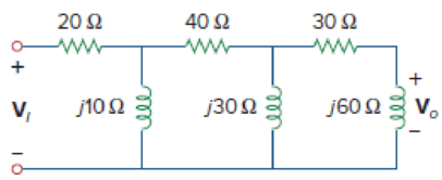
Figure 9.82
Expert Solution & Answer
Want to see the full answer?
Check out a sample textbook solution
Students have asked these similar questions
Find Va and Vb using Nodal analysis
Calculate the nodal voltage in the circuit
Calculate the mesh currents, find Ia, Ib, Ic. Apply mesh analysis
Chapter 9 Solutions
Fundamentals of Electric Circuits
Ch. 9.2 - Practice Problem 9.1 Given the sinusoid 45 cos(5t...Ch. 9.2 - Practice Problem 9.2 Find the phase angle between...Ch. 9.3 - Prob. 3PPCh. 9.3 - Express these sinusoids as phasors: (a)...Ch. 9.3 - Find the sinusoids corresponding to these phasors:...Ch. 9.3 - If v1=10sint30V and v2=20cost+45V, find v=v1+v2.Ch. 9.3 - Prob. 7PPCh. 9.4 - If voltage v=25sin100t15V is applied to a 50F...Ch. 9.5 - Refer to Fig. 9.17. Determine v(t) and i(t).Ch. 9.7 - Determine the input impedance of the circuit in...
Ch. 9.7 - Calculate vo in the circuit of Fig. 9.27. Figure...Ch. 9.7 - Find I in the circuit of Fig. 9.30. Figure 9.30Ch. 9.8 - Design an RC circuit to provide a 90 lagging phase...Ch. 9.8 - Refer to the RL circuit in Fig. 9.36. If 10 V is...Ch. 9.8 - In the ac bridge circuit of Fig. 9.37, suppose...Ch. 9 - Which of the following is not a right way to...Ch. 9 - A function that repeats itself after fixed...Ch. 9 - Which of these frequencies has the shorter period?...Ch. 9 - If v1 = 30 sin(t + 10) and v2 = 20 sin(t + 50),...Ch. 9 - The voltage across an inductor leads the current...Ch. 9 - The imaginary part of impedance is called:...Ch. 9 - The impedance of a capacitor increases with...Ch. 9 - At what frequency will the output voltage v0(t) in...Ch. 9 - A series RC circuit has VR = 12 V and VC = 5 V....Ch. 9 - A series RCL circuit has R = 30 , XC = 50 , and XL...Ch. 9 - Given the sinusoidal voltage v(t) = 50 cos (30t +...Ch. 9 - A current source in a linear circuit has...Ch. 9 - Express the following functions in cosine form:...Ch. 9 - Design a problem to help other students better...Ch. 9 - Given v1=45sint+30V and v2=50cost30V, determine...Ch. 9 - For the following pairs of sinusoids, determine...Ch. 9 - If f() = cos + j sin , show that f() = ej.Ch. 9 - Calculate these complex numbers and express your...Ch. 9 - Evaluate the following complex numbers and leave...Ch. 9 - Design a problem to help other students better...Ch. 9 - Find the phasors corresponding to the following...Ch. 9 - Let X=440 and Y=2030. Evaluate the following...Ch. 9 - Evaluate the following complex numbers: (a)...Ch. 9 - Simplify the following expression: (a)...Ch. 9 - Evaluate these determinants: (a) 10+j62j351+j (b)...Ch. 9 - Prob. 16PCh. 9 - Two voltages v1 and v2 appear in series so that...Ch. 9 - Obtain the sinusoids corresponding to each of the...Ch. 9 - Using phasors, find: (a) 3cos20t+105cos20t30 (b)...Ch. 9 - A linear network has a current input 7.5cos10t+30A...Ch. 9 - Simplify the following: (a) ft=5cos2t+154sin2t30...Ch. 9 - An alternating voltage is given by v(t) = 55...Ch. 9 - Apply phasor analysis to evaluate the following:...Ch. 9 - Find v(t) in the following integrodifferential...Ch. 9 - Using phasors, determine i(t) in the following...Ch. 9 - Prob. 26PCh. 9 - A parallel RLC circuit has the node equation...Ch. 9 - Determine the current that flows through an 20-...Ch. 9 - Given that vc(0) = 2 cos(155) V, what is the...Ch. 9 - A voltage v(t) = 100 cos(60t + 20) V is applied to...Ch. 9 - A series RLC circuit has R = 80 , L = 240 mH, and...Ch. 9 - Using Fig. 9.40, design a problem to help other...Ch. 9 - A series RL circuit is connected to a 220-V ac...Ch. 9 - What value of will cause the forced response, vo...Ch. 9 - Find the steady-state current i in the circuit of...Ch. 9 - Using Fig. 9.43, design a problem to help other...Ch. 9 - Determine the admittance Y for the circuit in Fig....Ch. 9 - Using Fig. 9.45, design a problem to help other...Ch. 9 - For the circuit shown in Fig. 9.46, find Zeq and...Ch. 9 - In the circuit of Fig. 9.47, find io when: (a) =...Ch. 9 - Find v(t) in the RLC circuit of Fig. 9.48. Figure...Ch. 9 - Calculate vo(t) in the circuit of Fig. 9.49....Ch. 9 - Find current Io in the circuit shown in Fig. 9.50....Ch. 9 - Calculate i(t) in the circuit of Fig. 9.51. Figure...Ch. 9 - Find current Io in the network of Fig. 9.52....Ch. 9 - If vs = 100 sin(10t + 18) V in the circuit of Fig....Ch. 9 - In the circuit of Fig. 9.54, determine the value...Ch. 9 - Given that vs(t) = 20 sin (100t 40) in Fig. 9.55,...Ch. 9 - Find vs (t) in the circuit of Fig. 9.56 if the...Ch. 9 - Determine vx in the circuit of Fig. 9.57. Let...Ch. 9 - If the voltage vo across the 2- resistor in the...Ch. 9 - If V in the circuit of Fig. 9.59, find Is. Figure...Ch. 9 - Find Io in the circuit of Fig. 9.60.Ch. 9 - In the circuit of Fig. 9.61, Find Vs if Io=300A.Ch. 9 - Find Z in the network of Fig. 9.62, given that...Ch. 9 - At = 377 rad/s, find the input impedance of the...Ch. 9 - At = 1 rad/s, obtain the input admittance in the...Ch. 9 - Using Fig. 9.65, design a problem to help other...Ch. 9 - For the network in Fig. 9.66, find Zin. Let = 100...Ch. 9 - Obtain Zin for the circuit in Fig. 9.67. Figure...Ch. 9 - Find Zeq in the circuit in Fig. 9.68. Figure 9.68Ch. 9 - For the circuit in Fig. 9.69, find the input...Ch. 9 - For the circuit in Fig. 9.70, find the value of...Ch. 9 - Find ZT and Vo in the circuit in Fig. 9.71. Let...Ch. 9 - Determine ZT and I for the circuit in Fig. 9.72....Ch. 9 - For the circuit in Fig. 9.73, calculate ZT and...Ch. 9 - At = 103 rad/s, find the input admittance of each...Ch. 9 - Determine Yeq for the circuit in Fig. 9.75. Figure...Ch. 9 - Find the equivalent admittance Yeq of the circuit...Ch. 9 - Find the equivalent impedance of the circuit in...Ch. 9 - Obtain the equivalent impedance of the circuit in...Ch. 9 - Calculate the value of Zab in the network of Fig....Ch. 9 - Determine the equivalent impedance of the circuit...Ch. 9 - Design an RL circuit to provide a 90 leading phase...Ch. 9 - Design a circuit that will transform a sinusoidal...Ch. 9 - For the following pairs of signals, determine if...Ch. 9 - Refer to the RC circuit in Fig. 9.81. (a)...Ch. 9 - A coil with impedance 8 + j6 is connected in...Ch. 9 - (a) Calculate the phase shift of the circuit in...Ch. 9 - Consider the phase-shifting circuit in Fig. 9.83....Ch. 9 - The ac bridge in Fig. 9.37 is balanced when R1 =...Ch. 9 - A capacitance bridge balances when R1 = 100 , R2 =...Ch. 9 - An inductive bridge balances when R1 = 1.2 k, R2 =...Ch. 9 - The ac bridge shown in Fig. 9.84 is known as a...Ch. 9 - The ac bridge circuit of Fig. 9.85 is called a...Ch. 9 - The circuit shown in Fig. 9.86 is used in a...Ch. 9 - The network in Fig. 9.87 is part of the schematic...Ch. 9 - A series audio circuit is shown in Fig. 9.88. (a)...Ch. 9 - An industrial load is modeled as a series...Ch. 9 - An industrial coil is modeled as a series...Ch. 9 - Figure 9.91 shows a series combination of an...Ch. 9 - A transmission line has a series impedance of and...Ch. 9 - A power transmission system is modeled as shown in...
Knowledge Booster


Learn more about
Need a deep-dive on the concept behind this application? Look no further. Learn more about this topic, electrical-engineering and related others by exploring similar questions and additional content below.Similar questions
- Find Va and Vb using Nodal analysisarrow_forward4. A battery operated sensor transmits to a receiver that is plugged in to a power outlet. The device is continuously operated. The battery is a 3.6 V coin-cell battery with a 245mAHr capacity. The application requires a bit rate of 36 Mbps and an error rate of less than 10^-3. The channel has a center frequency of 2.4 GHz, a bandwidth of 10 MHz and a noise power spectral density of 10^-14 W/Hz. The maximum distance is 36 meters and the losses in the channel attenuates the signal by 0.25 dB/meter. Your company has two families of chips that you can use. An M-ary ASK and an M-ary QAM chip. The have very different power requirements as shown in the table below. The total current for the system is the current required to achieve the desired Eb/No PLUS the current identified below: Hokies PSK Chip Set Operating Current NOT Including the required Eb/No for the application Hokies QAM Chip Set Operating Current NOT Including the required Eb/No for the application Chip ID M-ary Voltage (volts)…arrow_forwardUsing the 802.11a specifications given below, in Matlab (or similar tool) create the time domain signal for one OFDM symbol using QPSK modulation. See attached plot for the QPSK constellation. Your results should include the power measure in the time and frequency domain and comment on those results. BW 802.11a OFDM PHY Parameters 20 MHZ OBW Subcarrer Spacing Information Rate Modulation Coding Rate Total Subcarriers Data Subcarriers Pilot Subcarriers DC Subcarrier 16.6 MHZ 312.5 Khz (20MHz/64 Pt FFT) 6/9/12/18/24/36/48/54 Mbits/s BPSK, QPSK, 16QAM, 64QAM 1/2, 2/3, 3/4 52 (Freq Index -26 to +26) 48 4 (-21, -7, +7, +21) *Always BPSK Null (0 subcarrier) 52 subarriers -7 (48 Data, 4 Pilot (BPSK), 1 Null) -26 -21 0 7 21 +26 14 One Subcarrier 1 OFDM symbol 1 OFDM Burst -OBW 16.6 MHz BW 20 MHZ 1 constellation point = 52 subcarriers = one or more OFDM symbols 802.11a OFDM Physical Parameters Show signal at this point x bits do Serial Data d₁ S₁ Serial-to- Input Signal Parallel Converter IFFT…arrow_forward
- Find Vb and Va using Mesh analysisarrow_forward1. The communication channel bandwidth is 25 MHz centered at 1GHz and has a noise power spectral density of 10^-9 W/Hz. The channel loss between the transmitter and receiver is 25dB. The application requires a bit rate of 200Mbps and BER of less than 10^-4. Excluding Mary FSK, Determine the minimum transmit power required.arrow_forward2. An existing system uses noncoherent BASK. The application requires a BER of <10^-5. The current transmit power is 25 Watts. If the system changes to a coherent BPSK modulation scheme, what is the new transmit power required to deliver the same BER?arrow_forward
- 3. You are to design a 9-volt battery operated communication system that must last 3 years without replacing batteries. The communication channel bandwidth is 100 KHz centered at 5.8 GHz. The application requires a BER of <10^-5 and a data rate of 1 Mbps. The channel can be modeled as AWGN with a noise power spectral density of 10^-8 W/Hz. ((a) What modulation scheme would you use? B) what is the required capacity of the batteries? and (c) is the battery commercially available?arrow_forwardDesign a traffic light PIC microcontroller program with Green LED has 3 Sec Yellow LED has 0.5 Sec Red LED has 3 Sec RASAN4SSC20UT 8 RBOINT RB1 9 RB2 U1 PIC16F877A-I/PT 18 19 MCLRVPP RAOANO 20 RA1AN1 30 OSCICLKI 21 RAZAN2VREF-CVREF 31 OSC2CLKO RABAN3VREF+ 22 LED1 LED-3MM 〃 R1 330 RA4TOCKIC1OUT 23 7 VDD 28 VDD 6 VSS 29 VSS 24 LED2 LED-3MM R2 10 330 RB3PGM 11 + 14 RB4 38 RDOPSPO RB5 15 LED3 39 RD1PSP1 40 RD2PSP2 RB6PGC- RB7PGD 17 16 LED-3MM R3 330 41 RD3PSP3 2 RD4PSP4 RCOT1OSOTICKK 3 RDSPSPS RC1T10SICCP24 RD6PSP6 RC2CCP1 5 RD7PSP7 RC3SCKSCL RC4SDISDA 25 REORDANS RCSSDO 27 29 REIWRANG RC6TXCK- RE2CSAN7 RC7RXDT DAWWWW 32 35 36 37 42 43 44 1 12 NO 13 NC 33 NO 34 NCarrow_forward: +0 العنوان I need a detailed drawing with explanation しじ ined sove in peaper Anoting Q4// Draw and Evaluate √√√xy-²sin(y²)dydx PU+96er Lake Ge Q3// Find the volume of the region between the cylinder 2 = y² and the xy- plane that is bounded by the planes x = 1, x = 2, y = -2, and y = 2. T Marrow_forward
arrow_back_ios
SEE MORE QUESTIONS
arrow_forward_ios
Recommended textbooks for you
 Delmar's Standard Textbook Of ElectricityElectrical EngineeringISBN:9781337900348Author:Stephen L. HermanPublisher:Cengage Learning
Delmar's Standard Textbook Of Electricity
Electrical Engineering
ISBN:9781337900348
Author:Stephen L. Herman
Publisher:Cengage Learning
02 - Sinusoidal AC Voltage Sources in Circuits, Part 1; Author: Math and Science;https://www.youtube.com/watch?v=8zMiIHVMfaw;License: Standard Youtube License