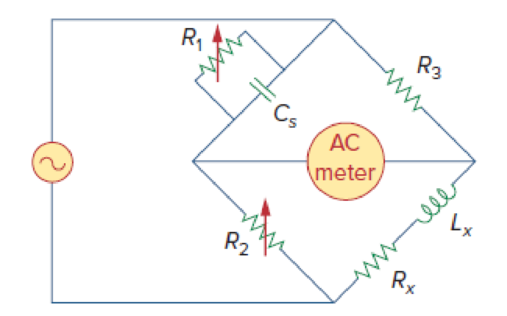
The ac bridge shown in Fig. 9.84 is known as a Maxwell bridge and is used for accurate measurement of inductance and resistance of a coil in terms of a standard capacitance Cs. Show that when the bridge is balanced,
Lx = R2R3Cs and
Find Lx and Rx for R1 = 40 kΩ, R2 = 1.6 kΩ, R3 = 4 kΩ, and Cs = 0.45 μF.

Figure 9.84
Show that when the bridge in Figure 9.85 is balanced the value of resistor
Answer to Problem 84P
The value of resistor
Explanation of Solution
Given data:
Refer to Figure 9.85 in the textbook.
The value of resistor
The value of resistor
The value of resistor
The value of capacitor
Formula used:
Write a general expression to calculate the impedance of a resistor.
Here,
Write a general expression to calculate the impedance of an inductor.
Here,
Write a general expression to calculate the impedance of a capacitor.
Here,
Calculation:
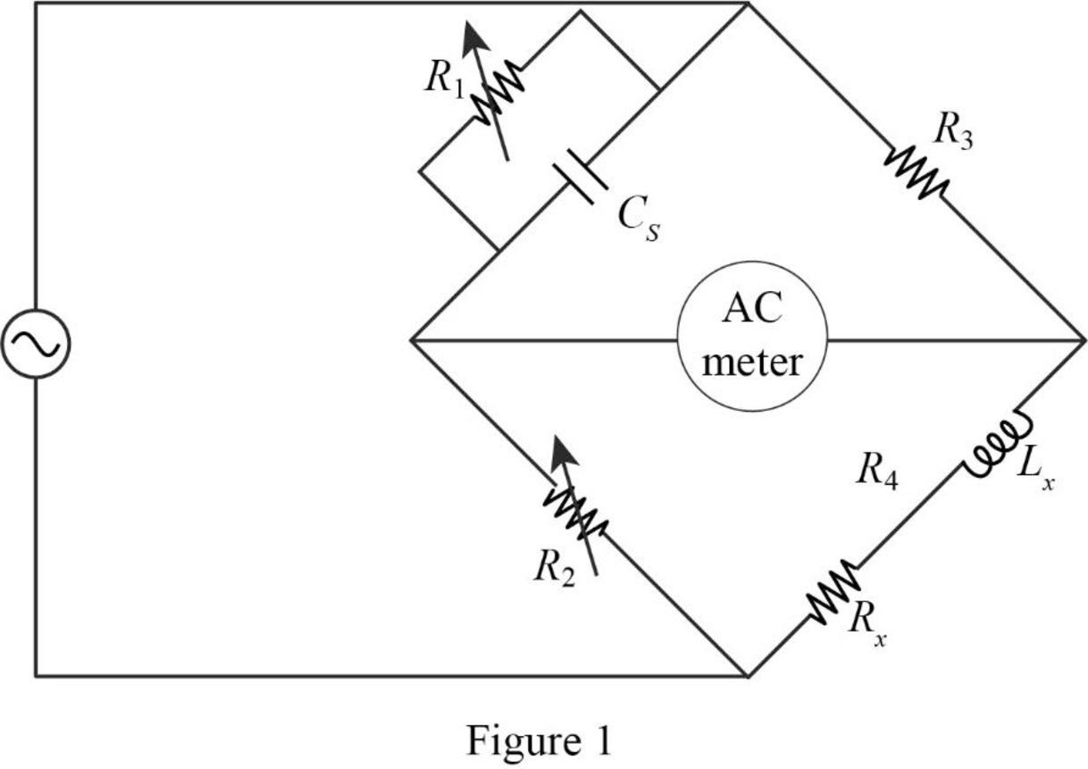
The given circuit is redrawn as shown in Figure 1.

Use equation (1) to find
Use equation (2) to find
Use equation (3) to find
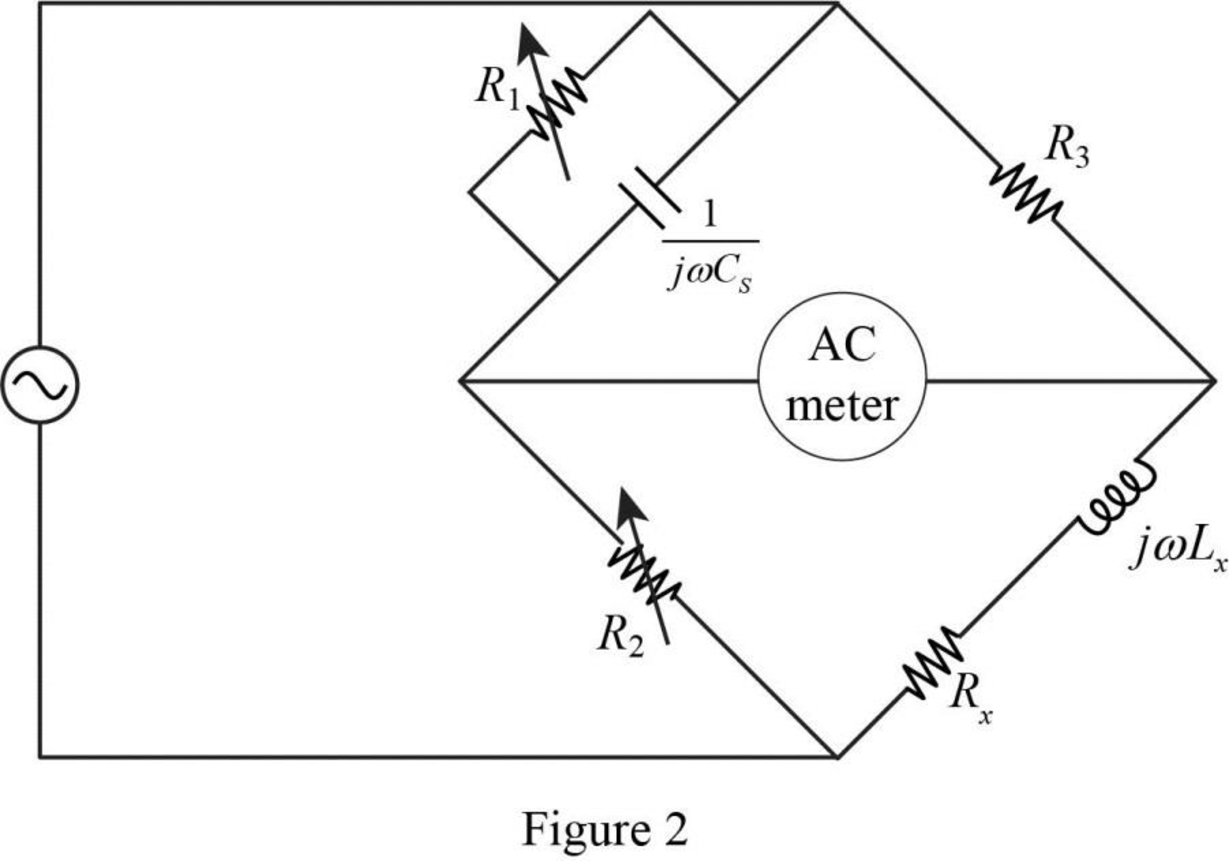
Now, the impedance diagram of Figure 1 is drawn as shown in Figure 2.

Refer to Figure 2, the impedance of resistor
Therefore, the equivalent impedance
Refer to Figure 2, the impedance of resistor
The equivalent impedance
Let,
The balance of equation of an ac bridge is,
Substitute
Equate the real and imaginary part in above equation.
Simplify the equation (5) to find
Substitute
Substitute
Conclusion:
Thus, when the bridge is balanced, the value of resistor
Want to see more full solutions like this?
Chapter 9 Solutions
Fundamentals of Electric Circuits
- 15arrow_forwardGiven the following, assume 0.7 V votlage drop across LEDs when they are positively biased.(a) When VB=0V, which LED is on?(b) When VB=5V, which LED is on?(c) If you want to limit the current through the LEDs to 10mA for both cases of 3(a) and 3 (b), find out the resistor values of RG and RR.arrow_forwardGiven the following, the intial condtion of output Q is high (H). (a) When /ALM is pushed on, creating a short to ground, what are the inputvoltages of S and R, and the output voltage Q?(b) After (a) happens, /ALM is released. What is the output voltage Q?(c) After (a) and (b) happen, /RESET is pushed on, creating a short to ground,what are the input voltages of S and R, and the output voltage Q?(d) After (a), (b) and (c) happen, /RESET is released. What is the output voltageQ?arrow_forward
 Delmar's Standard Textbook Of ElectricityElectrical EngineeringISBN:9781337900348Author:Stephen L. HermanPublisher:Cengage Learning
