
Videos
Figure 9.91 shows a series combination of an inductance and a resistance. If it is desired to connect a capacitor in parallel with the series combination such that the net impedance is resistive at 10 kHz, what is the required value of C?
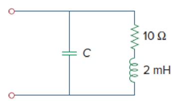
Figure 9.91
Find the value of capacitor
Answer to Problem 91CP
When the net impedance is resistive at a frequency of
Explanation of Solution
Given data:
Refer to Figure 9.89 in the textbook.
The value of frequency
Formula used:
Write a general expression to calculate the impedance of a resistor.
Here,
Write a general expression to calculate the impedance of an inductor.
Here,
Write a general expression to calculate the impedance of a capacitor.
Here,
Write a general formula to calculate the angular frequency.
Here,
Calculation:
Refer to the given circuit, the value of resistor
In the given circuit, the series of combination of resistor and inductor is connected in parallel with the capacitor.
The equivalent impedance of the given circuit is written as follows using equation (1), (2) and (3).
Simplify the above equation as follows:
Simplify the above equation as follows:
The equivalent impedance must be resistive when
Equate the imaginary part of above equation to zero.
Simplify the above equation as follows:
Simplify the above equation to find
Substitute
Substitute
Simplify the above equation as follows:
Conclusion:
Thus, When the net impedance is resistive at a frequency of
Want to see more full solutions like this?
Chapter 9 Solutions
Fundamentals of Electric Circuits


- A17)arrow_forwardUsing Carson's rule, determine the transmission bandwidth for commercial FM radio broadcasting, provided that the maximum value of frequency deviation is 75 kHz and the bandwidth of the audio signal is 15 kHzarrow_forward2. Laboratory Preliminary Discussion First-order High-pass RC Filter Analysis The first-order high-pass RC filter shown in figure 3 below represents all voltages and currents in the time domain. We will again convert the circuit to its s-domain equivalent as shown in figure 4 and apply Laplace transform techniques. ic(t) C vs(t) i₁(t) + + vc(t) R1 ww Vi(t) || 12(t) V2(t) R₂ Vout(t) VR2(t) = V2(t) Figure 3: A first-order high-pass RC filter represented in the time domain. Ic(s) C + Vs(s) I₁(s) + + Vc(s) R₁ www V₁(s) 12(s) V₂(s) R₂ Vout(S) = VR2(S) = V2(s) Figure 4: A first-order high-pass RC filter represented in the s-domain. Again, to generate the s-domain expression for the output voltage, You (S) = V2 (s), for the circuit shown in figure 4 above, we can apply voltage division in the s-domain as shown in equation 2 below. Equation 2 will be used in the prelab computations to find an expression for the output voltage, xc(t), in the time domain. equation (2) R₂ Vout(s) = V₂(s) = R₂+…arrow_forward
- Can you show me the steps to get the last part after the second equal sign.arrow_forwardPrelab Information 1. Laboratory Preliminary Discussion First-order Low-pass RC Filter Analysis The first-order low-pass RC filter shown in figure 1 below represents all voltages and currents in the time domain. It is of course possible to solve for all circuit voltages using time domain differential equation techniques, but it is more efficient to convert the circuit to its s-domain equivalent as shown in figure 2 and apply Laplace transform techniques. vs(t) i₁(t) + R₁ ww V₁(t) 12(t) Lic(t) Vout(t) = V2(t) R₂ Vc(t) C Vc(t) VR2(t) = V2(t) + Vs(s) Figure 1: A first-order low-pass RC filter represented in the time domain. I₁(s) R1 W + V₁(s) V₂(s) 12(s) Ic(s) + Vout(S) == Vc(s) Vc(s) Zc(s) = = VR2(S) V2(s) Figure 2: A first-order low-pass RC filter represented in the s-domain.arrow_forwardA.15 Consider a communication channel, transfer characteristic of which is defined by the nonlinear relation, y(t) = x(t) + x² (t), where x(t) is the input and y(t) is the output. Assuming the input is an FM signal, x(t) = cos (2лft+(t)), find y(t). Is it possible to retrieve x(t) from y(t)? If so, how?arrow_forward
- 1) Show that a regenerative receiver can be used to recover message from the following modulated signals. a. DSB-PC b. DSB-SC 1b) Does the receiver need to recover the carrier phase? 1c) What are the filtering requirements and restrictions on message signal bandwidth and carrier frequency.arrow_forward2) Estimate the transmission bandwidth for the following FM modulated signals (W is the message bandwidth) a) W1KHz and frequency deviation of 75KHz b) W = 20KHz and frequency deviation of 75KHz c) W1KHz and frequency deviation of 150KHz d) W20KHz and frequency deviation of 150KHZarrow_forwardI want to explain how the result becomes (735.1) Hz) and what are the steps and explain the reasons? Q6 The FET shown in Fig. 1.43 has gm = 3.4mS and ra =100 K. Find the approximate lower cutoff frequency. Ans: 735.1 Hz. 25V 2ΚΩ 1.5ΜΩ 0.02µF 0.02µF 20 ΚΩ 330kQ 820 ΩΣ OpF Fig. 1.43 Circuit for Q6. 40ΚΩarrow_forward
 Delmar's Standard Textbook Of ElectricityElectrical EngineeringISBN:9781337900348Author:Stephen L. HermanPublisher:Cengage Learning