
Fundamentals of Electric Circuits
6th Edition
ISBN: 9780078028229
Author: Charles K Alexander, Matthew Sadiku
Publisher: McGraw-Hill Education
expand_more
expand_more
format_list_bulleted
Videos
Textbook Question
Chapter 9.5, Problem 9PP
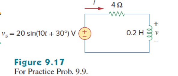
Refer to Fig. 9.17. Determine v(t) and i(t).
Expert Solution & Answer
Want to see the full answer?
Check out a sample textbook solution
Students have asked these similar questions
Q3/A 8-pole, 3-phase, 50 Hz induction motor, running at 725 r.p.m, rotor is star connected its resistance and reactance 0.25 and 1.5 ohm per phase, the emf between slip rings is 100, find the rotor current per phase, power factor, synchronous speed, slip and rotor frequency
440 v, 4-pole, 3-phase, 50 Hz, star stator connected induction motor, full load speed 1425 r.p.m, rotor impedance 0.5+4.55ohm and rotor/stator ratio 0.8 calculate 1) starting torque, (2) rotor current (3) the value of external resistance to add to give maximum starting torque (4) power factor at maximum torque.
I would like to know the gear ratio and the tractive effort that a trolley must achieve with the following motor specifications:
Voltage: 600 voltsSpeed: 1750 to 2300 RPMCurrent: 84 AmpsRated Power: 50-55 HP
What percentage should be considered for gear efficiency, and what safe margin should be applied in these calculations?
The constraints for the truck trolley are as follows:Maximum Speed: 50 MPHWeight of the Car Body: 46,000 lbs (the trolley weighs approximately 44,000 lbs)Diameter wheels: 86 inchesAdditionally, I would like to know how to plot a graph of tractive effort (in grams) versus speed (in MPH).
Chapter 9 Solutions
Fundamentals of Electric Circuits
Ch. 9.2 - Practice Problem 9.1 Given the sinusoid 45 cos(5t...Ch. 9.2 - Practice Problem 9.2 Find the phase angle between...Ch. 9.3 - Prob. 3PPCh. 9.3 - Express these sinusoids as phasors: (a)...Ch. 9.3 - Find the sinusoids corresponding to these phasors:...Ch. 9.3 - If v1=10sint30V and v2=20cost+45V, find v=v1+v2.Ch. 9.3 - Prob. 7PPCh. 9.4 - If voltage v=25sin100t15V is applied to a 50F...Ch. 9.5 - Refer to Fig. 9.17. Determine v(t) and i(t).Ch. 9.7 - Determine the input impedance of the circuit in...
Ch. 9.7 - Calculate vo in the circuit of Fig. 9.27. Figure...Ch. 9.7 - Find I in the circuit of Fig. 9.30. Figure 9.30Ch. 9.8 - Design an RC circuit to provide a 90 lagging phase...Ch. 9.8 - Refer to the RL circuit in Fig. 9.36. If 10 V is...Ch. 9.8 - In the ac bridge circuit of Fig. 9.37, suppose...Ch. 9 - Which of the following is not a right way to...Ch. 9 - A function that repeats itself after fixed...Ch. 9 - Which of these frequencies has the shorter period?...Ch. 9 - If v1 = 30 sin(t + 10) and v2 = 20 sin(t + 50),...Ch. 9 - The voltage across an inductor leads the current...Ch. 9 - The imaginary part of impedance is called:...Ch. 9 - The impedance of a capacitor increases with...Ch. 9 - At what frequency will the output voltage v0(t) in...Ch. 9 - A series RC circuit has VR = 12 V and VC = 5 V....Ch. 9 - A series RCL circuit has R = 30 , XC = 50 , and XL...Ch. 9 - Given the sinusoidal voltage v(t) = 50 cos (30t +...Ch. 9 - A current source in a linear circuit has...Ch. 9 - Express the following functions in cosine form:...Ch. 9 - Design a problem to help other students better...Ch. 9 - Given v1=45sint+30V and v2=50cost30V, determine...Ch. 9 - For the following pairs of sinusoids, determine...Ch. 9 - If f() = cos + j sin , show that f() = ej.Ch. 9 - Calculate these complex numbers and express your...Ch. 9 - Evaluate the following complex numbers and leave...Ch. 9 - Design a problem to help other students better...Ch. 9 - Find the phasors corresponding to the following...Ch. 9 - Let X=440 and Y=2030. Evaluate the following...Ch. 9 - Evaluate the following complex numbers: (a)...Ch. 9 - Simplify the following expression: (a)...Ch. 9 - Evaluate these determinants: (a) 10+j62j351+j (b)...Ch. 9 - Prob. 16PCh. 9 - Two voltages v1 and v2 appear in series so that...Ch. 9 - Obtain the sinusoids corresponding to each of the...Ch. 9 - Using phasors, find: (a) 3cos20t+105cos20t30 (b)...Ch. 9 - A linear network has a current input 7.5cos10t+30A...Ch. 9 - Simplify the following: (a) ft=5cos2t+154sin2t30...Ch. 9 - An alternating voltage is given by v(t) = 55...Ch. 9 - Apply phasor analysis to evaluate the following:...Ch. 9 - Find v(t) in the following integrodifferential...Ch. 9 - Using phasors, determine i(t) in the following...Ch. 9 - Prob. 26PCh. 9 - A parallel RLC circuit has the node equation...Ch. 9 - Determine the current that flows through an 20-...Ch. 9 - Given that vc(0) = 2 cos(155) V, what is the...Ch. 9 - A voltage v(t) = 100 cos(60t + 20) V is applied to...Ch. 9 - A series RLC circuit has R = 80 , L = 240 mH, and...Ch. 9 - Using Fig. 9.40, design a problem to help other...Ch. 9 - A series RL circuit is connected to a 220-V ac...Ch. 9 - What value of will cause the forced response, vo...Ch. 9 - Find the steady-state current i in the circuit of...Ch. 9 - Using Fig. 9.43, design a problem to help other...Ch. 9 - Determine the admittance Y for the circuit in Fig....Ch. 9 - Using Fig. 9.45, design a problem to help other...Ch. 9 - For the circuit shown in Fig. 9.46, find Zeq and...Ch. 9 - In the circuit of Fig. 9.47, find io when: (a) =...Ch. 9 - Find v(t) in the RLC circuit of Fig. 9.48. Figure...Ch. 9 - Calculate vo(t) in the circuit of Fig. 9.49....Ch. 9 - Find current Io in the circuit shown in Fig. 9.50....Ch. 9 - Calculate i(t) in the circuit of Fig. 9.51. Figure...Ch. 9 - Find current Io in the network of Fig. 9.52....Ch. 9 - If vs = 100 sin(10t + 18) V in the circuit of Fig....Ch. 9 - In the circuit of Fig. 9.54, determine the value...Ch. 9 - Given that vs(t) = 20 sin (100t 40) in Fig. 9.55,...Ch. 9 - Find vs (t) in the circuit of Fig. 9.56 if the...Ch. 9 - Determine vx in the circuit of Fig. 9.57. Let...Ch. 9 - If the voltage vo across the 2- resistor in the...Ch. 9 - If V in the circuit of Fig. 9.59, find Is. Figure...Ch. 9 - Find Io in the circuit of Fig. 9.60.Ch. 9 - In the circuit of Fig. 9.61, Find Vs if Io=300A.Ch. 9 - Find Z in the network of Fig. 9.62, given that...Ch. 9 - At = 377 rad/s, find the input impedance of the...Ch. 9 - At = 1 rad/s, obtain the input admittance in the...Ch. 9 - Using Fig. 9.65, design a problem to help other...Ch. 9 - For the network in Fig. 9.66, find Zin. Let = 100...Ch. 9 - Obtain Zin for the circuit in Fig. 9.67. Figure...Ch. 9 - Find Zeq in the circuit in Fig. 9.68. Figure 9.68Ch. 9 - For the circuit in Fig. 9.69, find the input...Ch. 9 - For the circuit in Fig. 9.70, find the value of...Ch. 9 - Find ZT and Vo in the circuit in Fig. 9.71. Let...Ch. 9 - Determine ZT and I for the circuit in Fig. 9.72....Ch. 9 - For the circuit in Fig. 9.73, calculate ZT and...Ch. 9 - At = 103 rad/s, find the input admittance of each...Ch. 9 - Determine Yeq for the circuit in Fig. 9.75. Figure...Ch. 9 - Find the equivalent admittance Yeq of the circuit...Ch. 9 - Find the equivalent impedance of the circuit in...Ch. 9 - Obtain the equivalent impedance of the circuit in...Ch. 9 - Calculate the value of Zab in the network of Fig....Ch. 9 - Determine the equivalent impedance of the circuit...Ch. 9 - Design an RL circuit to provide a 90 leading phase...Ch. 9 - Design a circuit that will transform a sinusoidal...Ch. 9 - For the following pairs of signals, determine if...Ch. 9 - Refer to the RC circuit in Fig. 9.81. (a)...Ch. 9 - A coil with impedance 8 + j6 is connected in...Ch. 9 - (a) Calculate the phase shift of the circuit in...Ch. 9 - Consider the phase-shifting circuit in Fig. 9.83....Ch. 9 - The ac bridge in Fig. 9.37 is balanced when R1 =...Ch. 9 - A capacitance bridge balances when R1 = 100 , R2 =...Ch. 9 - An inductive bridge balances when R1 = 1.2 k, R2 =...Ch. 9 - The ac bridge shown in Fig. 9.84 is known as a...Ch. 9 - The ac bridge circuit of Fig. 9.85 is called a...Ch. 9 - The circuit shown in Fig. 9.86 is used in a...Ch. 9 - The network in Fig. 9.87 is part of the schematic...Ch. 9 - A series audio circuit is shown in Fig. 9.88. (a)...Ch. 9 - An industrial load is modeled as a series...Ch. 9 - An industrial coil is modeled as a series...Ch. 9 - Figure 9.91 shows a series combination of an...Ch. 9 - A transmission line has a series impedance of and...Ch. 9 - A power transmission system is modeled as shown in...
Knowledge Booster


Learn more about
Need a deep-dive on the concept behind this application? Look no further. Learn more about this topic, electrical-engineering and related others by exploring similar questions and additional content below.Similar questions
- A scientist proposed building an EM wave as E= 6000 sin (300 x -5000t) j + 6000 sin (300 x -5000t)k andB= -0.25 sin (300 x -5000t) i + 0.25 sin (300 x -5000t) k. Explain why this is not possible and explain all the mistakes E= 6000 sin (300 x -wt) j . Find the value for w and find the magnetic field vector and the Poynting vector as afunction of x and t.arrow_forwardSolve this problem and show all of the workarrow_forwardSolve this problem and show all of the workarrow_forward
- 2. A system with unity feedback is shown below. The feed-forward transfer function is G(s), where 5 . G(S) = (+1) Sketch the root locus for the variations in the values of pi. (s+P1)s R(s) C(s) G(s)arrow_forward3. The following closed-loop systems in Fig. 1 and Fig. 2 operate with a damping ratio of 0.707 (=0.707). The system in Fig. 1 does not have a PI controller, while the one in Fig. 2 does. R(s): S Gain Plant R(s) + E(s) 1 C(s) K (s+1)(s+2)(s+10) Fig. 1: Closed-loop system without PI controller Compensator Plant R(s) + E(s) K(s+0.1) S 1 (s+1)(s+2)(s+10) C(s) Fig. 2: Closed-loop system with a practical PI controller a. Please use Matlab to find the intersection point between line and the root locus of the system in Fig. 1. Then find the K value and one complex closed-loop pole corresponding to the intersection point. Calculate the steady-state error. Show the Matlab code in your answer sheet. b. Please use Matlab to find the intersection point between § line and the root locus of the system in Fig. 2. Then find the K value and one complex closed-loop pole associated with the intersection point. Compare the complex closed-loop pole with the one you just found in task a. Are they very…arrow_forward1. Please draw the root locus by hand for the following closed-loop system, where G(s) = s+6 = S-2 s+8 s-2' and H(s) = Find the range of K for stability using Method II in Examples 2 and 3 in Lecture 15. Input R(s) Output C(s) KG(s) H(s)arrow_forward
- 9-1) Lathi & Ding, Prob. P.5.1-10 (a) A first-order-hold circuit can also be used to reconstruct a signal g(t) from its samples. The impulse response of this circuit is h(t) = A ( 2Ts 12 where Ts is the sampling interval. Consider a typical sampled signal ğ(t) and show that this circuit performs the linear interpolation. In other words, the filter output consists of sample tops connected by straight-line segments. Follow the procedure discussed in Sec. 5.1.2 (Fig. 5.6) for a typical signal g(t). (b) Determine the transfer function of this filter and its amplitude response, and compare it with the ideal filter required for signal reconstruction.arrow_forwardI have this rough circuit diagram of a 2 double end trolley light system with a 120 dcv power supply. I would like to know in what way is better to connect the interior lights along with the headlight and door light. Provide the circuit diagram and with its respect connection and the estimated total power rated for the lights. Where: Headlights (2) = #1 and #6Door lights (4) = #2, #4, #5, and #7Platform lights (2) = #3 and #8Interior lights are approximately 20 in quantity. Also, can you say if the components that are in series with the power supply are correct or does it need to be replaced with something else or if it is missing any components.arrow_forwardA domestic load of 2300 kW at 0.88 p.f lagging and a motors load of 3400 kW at 0.85 p.f lagging are supplied by two alternators operating in parallel. If one alternator is delivering a load of 3300 kW at 0.9 p.f lagging, what will be the output power and p.f of the other alternator?arrow_forward
- 9-3) similar to Lathi & Ding, Prob. P.5.2-3 In a satellite radio system, 200 stereo stations are to be packaged in one data stream. For each station, two (left & right) signals of bandwidth 22 kHz are sampled, quantized, and binary-coded into PCM signals. The transmitter then multiplexes the data from the 200 stations into a single stream via TDM and modulates that stream onto a radio carrier using DSB-SC-AM. (a) If the maximum acceptable quantization error is 0.25% of the peak signal voltage, find the minimum number of bits needed for a uniform quantizer. (b) If the sampling rate must be 25% higher than the Nyquist rate, find the minimum bit rate of the multiplexed data stream, based on the quantizer of part (a). (c) If 10% more bits are added for error correction and framing, determine the minimum bandwidth of the radio signal sent to the ground receivers.arrow_forward9-2) similar to Lathi & Ding, Prob. P.5.2-1 A compact disc (CD) records audio signals digitally by using PCM. Assume that the audio signal bandwidth equals 15 kHz. (a) If the Nyquist samples are uniformly quantized into L = 65, 536 levels and then binary-coded, determine the number of binary digits required to encode a sample. (b) if the audio signal has a peak voltage of ±1V and an average signal power of 0.1 V2, find the resulting ratio of signal to quantization noise (SQNR) for the system. (c) Determine the number of binary digits per second (bit/s) required to encode the audio signal. (d) For practical reasons discussed in the text, signals are sampled at a rate well above the Nyquist rate. Practical CDs use 44,100 samples per second. If L = 65,536, determine the number of bits per second required to encode the signal and the minimum bandwidth required to transmit the encoded signal.arrow_forward12.1 Evaluate each of the following integrals: (a) G₁ =√(31³ −4t²+3)[8(t) +28(t − 2)] dt. (b) G2=2(e³t +1)[8(t) −28(t − 2)] dt. 16 (c) G3 = √124t sin(2лt) − 1][§(t − 1)+8(t −6)] dt.|arrow_forward
arrow_back_ios
SEE MORE QUESTIONS
arrow_forward_ios
Recommended textbooks for you
 Delmar's Standard Textbook Of ElectricityElectrical EngineeringISBN:9781337900348Author:Stephen L. HermanPublisher:Cengage Learning
Delmar's Standard Textbook Of Electricity
Electrical Engineering
ISBN:9781337900348
Author:Stephen L. Herman
Publisher:Cengage Learning
02 - Sinusoidal AC Voltage Sources in Circuits, Part 1; Author: Math and Science;https://www.youtube.com/watch?v=8zMiIHVMfaw;License: Standard Youtube License