
Mechanics of Materials (MindTap Course List)
9th Edition
ISBN: 9781337093347
Author: Barry J. Goodno, James M. Gere
Publisher: Cengage Learning
expand_more
expand_more
format_list_bulleted
Concept explainers
Videos
Textbook Question
Chapter 7, Problem 7.3.21P
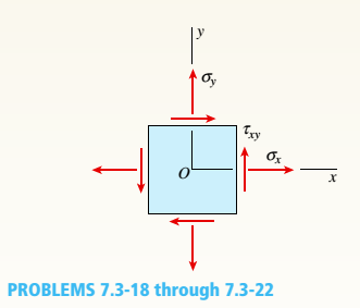
-18 through 7.3-22 An element in plane stress
(see figure) is subjected to stresses o, a., and
(a) Determine the principal stresses and show them on a sketch of a properly oriented element.
(b) Determine the maximum shear stresses and associated normal stresses and show them on a sketch of a properly oriented element.

Expert Solution & Answer
Want to see the full answer?
Check out a sample textbook solution
Students have asked these similar questions
A virtual experiment is designed to determine the effect of friction on the timing and speed
of packages being delivered to a conveyor belt and the normal force applied to the tube.
A package is held and then let go at the edge of a circular shaped tube of radius R = 5m.
The particle at the bottom will transfer to the conveyor belt, as shown below.
Run the simulations for μ = 0, 0.1, 0.2, 0.3, 0.4, 0.5, 0.6 and determine the time and speed at
which the package is delivered to the conveyor belt. In addition, determine the maximum
normal force and its location along the path as measured by angle 0.
Submit in hardcopy form:
(0) Free Body Diagram, equations underneath, derivations
(a) Your MATLAB mfile
(b) A table listing the values in 5 columns:
μ, T (time of transfer), V (speed of transfer), 0 (angle of max N), Nmax (max N)
(c) Based on your results, explain in one sentence what you think will happen to the
package if the friction is increased even further, e.g. μ = 0.8.
NOTE: The ODE is…
Patm = 1 bar
Piston
m = 50 kg
5 g of Air
T₁ = 600 K
P₁ = 3 bar
Stops
A 9.75 x 10⁻³ m²
FIGURE P3.88
Assume a Space Launch System (Figure 1(a)) that is approximated as a cantilever undamped single degree of freedom (SDOF) system with a mass at its free end (Figure 1(b)). The cantilever is assumed to be massless. Assume a wind load that is approximated with a concentrated harmonic forcing function p(t) = posin(ωt) acting on the mass. The known properties of the SDOF and the applied forcing function are given below. • Mass of SDOF: m =120 kip/g • Acceleration of gravity: g = 386 in/sec2 • Bending sectional stiffness of SDOF: EI = 1015 lbf×in2 • Height of SDOF: h = 2000 inches • Amplitude of forcing function: po = 6 kip • Forcing frequency: f = 8 H
Chapter 7 Solutions
Mechanics of Materials (MindTap Course List)
Ch. 7 - An clement m plane stress from the frame of a...Ch. 7 - Solve the preceding problem for an element in...Ch. 7 - The stresses on an element are sx= 1000 Psi. sy=...Ch. 7 - .4 The stresses on an clement arc known to be sx=...Ch. 7 - The stresses acting on element A on the web of a...Ch. 7 - Solve the preceding problem if the stresses acting...Ch. 7 - The stresses acting on element B on the web of a...Ch. 7 - An element in plane stress on the fuselage of an...Ch. 7 - The stresses acting on element B (see figure part...Ch. 7 - Solve the preceding problem if the normal and...
Ch. 7 - The polyethylene liner of a settling pond is...Ch. 7 - Solve the preceding problem if the norm al and...Ch. 7 - Two steel rods are welded together (see figure):...Ch. 7 - Repeat the previous problem using ? = 50° and...Ch. 7 - A rectangular plate of dimensions 3.0 in. × 5.0...Ch. 7 - Solve the preceding problem for a plate of...Ch. 7 - A simply supported beam is subjected to point load...Ch. 7 - Repeat the previous problem using sx= 12 MPa.Ch. 7 - At a point on the surface of an elliptical...Ch. 7 - Solve the preceding problem for sx= 11 MPa and...Ch. 7 - An clement m plane stress from the frame of a...Ch. 7 - Solve the preceding problem for the element shown...Ch. 7 - : A gusset plate on a truss bridge is in plane...Ch. 7 - The surface of an airplane wing is subjected to...Ch. 7 - At a point on the web of a girder on an overhead...Ch. 7 - -26 A rectangular plate of dimensions 125 mm × 75...Ch. 7 - -27 A square plate with side dimension of 2 in. is...Ch. 7 - The stresses acting on an element are x= 750 psi,...Ch. 7 - Repeat the preceding problem using sx= 5.5 MPa....Ch. 7 - An element in plane stress is subjected to...Ch. 7 - -4. - An element in plane stress is subjected to...Ch. 7 - An element in plane stress is subjected to...Ch. 7 - The stresses acting on element A in the web of a...Ch. 7 - The normal and shear stresses acting on element A...Ch. 7 - An element in plane stress from the fuselage of an...Ch. 7 - -9The stresses acting on element B in the web of a...Ch. 7 - The normal and shear stresses acting on element B...Ch. 7 - ‘7.3-11 The stresses on an element are sx= -300...Ch. 7 - - 7.3-12 A simply supported beam is subjected to...Ch. 7 - A shear wall in a reinforced concrete building is...Ch. 7 - The state of stress on an element along the...Ch. 7 - -15 Repeat the preceding problem using ??. = - 750...Ch. 7 - A propeller shaft subjected to combined torsion...Ch. 7 - 3-17 The stresses at a point along a beam...Ch. 7 - -18 through 7.3-22 An element in plane stress (see...Ch. 7 - -18 through 7.3-22 An element in plane stress (see...Ch. 7 - -18 through 7.3-22 An element in plane stress (see...Ch. 7 - -18 through 7.3-22 An element in plane stress (see...Ch. 7 - -18 through 7.3-22 An element in plane stress (see...Ch. 7 - At a point on the web of a girder on a gantry...Ch. 7 - The stresses acting on a stress element on the arm...Ch. 7 - The stresses at a point on the down tube of a...Ch. 7 - An element in plane stress on the surface of an...Ch. 7 - A simply supported wood beam is subjected to point...Ch. 7 - A simply supported wood beam is subjected to point...Ch. 7 - Prob. 7.4.1PCh. 7 - .4-2 An element in uniaxial stress is subjected to...Ch. 7 - An element on the gusset plate in Problem 7.2-23...Ch. 7 - An element on the top surface of the fuel tanker...Ch. 7 - An element on the top surface of the fuel tanker...Ch. 7 - An element in biaxial stress is subjected to...Ch. 7 - • - 7.4-7 An element on the surface of a drive...Ch. 7 - - A specimen used in a coupon test has norm al...Ch. 7 - A specimen used in a coupon test is shown in the...Ch. 7 - The rotor shaft of a helicopter (see figure part...Ch. 7 - An element in pure shear is subjected to stresses...Ch. 7 - An clement in plane stress is subjected to...Ch. 7 - Prob. 7.4.13PCh. 7 - An clement in plane stress is subjected to...Ch. 7 - An clement in plane stress is subjected to...Ch. 7 - An clement in plane stress is subjected to...Ch. 7 - Prob. 7.4.17PCh. 7 - -18 through 7.4-25 An clement in plane stress is...Ch. 7 - -18 through 7.4-25 An clement in plane stress is...Ch. 7 - Prob. 7.4.20PCh. 7 - -18 through 7.4-25 An clement in plane stress is...Ch. 7 - Through 7.4-25 An clement in plane stress is...Ch. 7 - -18 through 7.4-25 An clement in plane stress is...Ch. 7 - through 7.4-25 An clement in plane stress is...Ch. 7 - -18 through 7.4-25 An clement in plane stress is...Ch. 7 - 1 A rectangular steel plate with thickness t = 5/8...Ch. 7 - Solve the preceding problem if the thickness of...Ch. 7 - The state of stress on an element of material is...Ch. 7 - An element of a material is subjected to plane...Ch. 7 - Assume that the normal strains x and y , for an...Ch. 7 - A cast-iron plate in biaxial stress is subjected...Ch. 7 - Solve the preceding problem for a steel plate with...Ch. 7 - • - 3 A rectangular plate in biaxial stress (see...Ch. 7 - Solve the preceding problem for an aluminum plate...Ch. 7 - A brass cube of 48 mm on each edge is comp ressed...Ch. 7 - 7.5-11 in. cube of concrete (E = 4.5 X 10⁶ psi. v...Ch. 7 - -12 A square plate of a width h and thickness t is...Ch. 7 - Solve the preceding problem for an aluminum plate...Ch. 7 - A circle of a diameter d = 200 mm is etched on a...Ch. 7 - The normal stress on an elastomeric rubber pad in...Ch. 7 - A rubber sheet in biaxial stress is subjected to...Ch. 7 - An element of aluminum is subjected to tri-axial...Ch. 7 - An element of aluminum is subjected to tri- axial...Ch. 7 - -3 An element of aluminum in the form of a...Ch. 7 - Solve the preceding problem if the element is...Ch. 7 - A cube of cast iron with sides of length a = 4.0...Ch. 7 - Solve the preceding problem if the cube is granite...Ch. 7 - An element of aluminum is subjected to iriaxial...Ch. 7 - Prob. 7.6.8PCh. 7 - A rubber cylinder R of length L and cross-...Ch. 7 - A block R of rubber is confined between plane...Ch. 7 - -11 A rubber cube R of a side L = 3 in. and cross-...Ch. 7 - A copper bar with a square cross section is...Ch. 7 - A solid spherical ball of magnesium alloy (E = 6.5...Ch. 7 - A solid steel sphere (E = 210 GPa, v = 0.3) is...Ch. 7 - Prob. 7.6.15PCh. 7 - An element of material in plain strain has the...Ch. 7 - An clement of material in plain strain has the...Ch. 7 - An element of material in plain strain is...Ch. 7 - An element of material in plain strain is...Ch. 7 - A thin rectangular plate in biaxial stress is...Ch. 7 - Prob. 7.7.6PCh. 7 - A thin square plate in biaxial stress is subjected...Ch. 7 - Prob. 7.7.8PCh. 7 - An clement of material subjected to plane strain...Ch. 7 - Solve the preceding problem for the following...Ch. 7 - The strains for an element of material in plane...Ch. 7 - Solve the preceding problem for the following...Ch. 7 - An clement of material in plane strain (see...Ch. 7 - Solve the preceding problem for the following...Ch. 7 - A brass plate with a modulus of elastici ty E = 16...Ch. 7 - Solve the preceding problem if the plate is made...Ch. 7 - An element in plane stress is subjected to...Ch. 7 - Prob. 7.7.18PCh. 7 - During a test of an airplane wing, the strain gage...Ch. 7 - A strain rosette (see figure) mounted on the...Ch. 7 - A solid circular bar with a diameter of d = 1.25...Ch. 7 - A cantilever beam with a rectangular cross section...Ch. 7 - Solve the preceding problem if the cross-...Ch. 7 - A 600 strain rosette, or delta rosette, consists...Ch. 7 - On the surface of a structural component in a...Ch. 7 - - 7.2-26 The strains on the surface of an...Ch. 7 - Solve Problem 7.7-9 by using Mohr’s circle for...Ch. 7 - 7.7-28 Solve Problem 7.7-10 by using Mohr’s circle...Ch. 7 - Solve Problem 7.7-11 by using Mohr’s circle for...Ch. 7 - Solve Problem 7.7-12 by using Mohr’s circle for...Ch. 7 - Solve Problem 7.7-13 by using Mohr’s circle for...Ch. 7 - Prob. 7.7.32P
Knowledge Booster


Learn more about
Need a deep-dive on the concept behind this application? Look no further. Learn more about this topic, mechanical-engineering and related others by exploring similar questions and additional content below.Similar questions
- Assume a Space Launch System (Figure 1(a)) that is approximated as a cantilever undamped single degree of freedom (SDOF) system with a mass at its free end (Figure 1(b)). The cantilever is assumed to be massless. Assume a wind load that is approximated with a concentrated harmonic forcing function p(t) = posin(ωt) acting on the mass. The known properties of the SDOF and the applied forcing function are given below. • Mass of SDOF: m =120 kip/g • Acceleration of gravity: g = 386 in/sec2 • Bending sectional stiffness of SDOF: EI = 1015 lbf×in2 • Height of SDOF: h = 2000 inches • Amplitude of forcing function: po = 6 kip • Forcing frequency: f = 8 Hz Figure 1: Single-degree-of-freedom system in Problem 1. Please compute the following considering the steady-state response of the SDOF system. Do not consider the transient response unless it is explicitly stated in the question. (a) The natural circular frequency and the natural period of the SDOF. (10 points) (b) The maximum displacement of…arrow_forwardAssume a Space Launch System (Figure 1(a)) that is approximated as a cantilever undamped single degree of freedom (SDOF) system with a mass at its free end (Figure 1(b)). The cantilever is assumed to be massless. Assume a wind load that is approximated with a concentrated harmonic forcing function p(t) = posin(ωt) acting on the mass. The known properties of the SDOF and the applied forcing function are given below. • Mass of SDOF: m =120 kip/g • Acceleration of gravity: g = 386 in/sec2 • Bending sectional stiffness of SDOF: EI = 1015 lbf×in2 • Height of SDOF: h = 2000 inches • Amplitude of forcing function: po = 6 kip • Forcing frequency: f = 8 Hz Figure 1: Single-degree-of-freedom system in Problem 1. Please compute the following considering the steady-state response of the SDOF system. Do not consider the transient response unless it is explicitly stated in the question. (a) The natural circular frequency and the natural period of the SDOF. (10 points) (b) The maximum displacement of…arrow_forwardPlease solve 13 * √(2675.16)² + (63.72 + 2255,03)² = 175x106 can you explain the process for getting d seperate thank youarrow_forward
- If the 300-kg drum has a center of mass at point G, determine the horizontal and vertical components of force acting at pin A and the reactions on the smooth pads C and D. The grip at B on member DAB resists both horizontal and vertical components of force at the rim of the drum. P 60 mm; 60 mm: 600 mm A E 30° B C 390 mm 100 mm D Garrow_forwardThe design of the gear-and-shaft system shown requires that steel shafts of the same diameter be used for both AB and CD. It is further required that the angle D through which end D of shaft CD rotates not exceed 1.5°. Knowing that G = 77.2 GPa, determine the required diameter of the shafts. 40 mm 400 mm 100 mm 600 mm T-1000 N-m Darrow_forwardAssume a Space Launch System (Figure 1(a)) that is approximated as a cantilever undamped single degree of freedom (SDOF) system with a mass at its free end (Figure 1(b)). The cantilever is assumed to be massless. Assume a wind load that is approximated with a concentrated harmonic forcing function p(t) = posin(ωt) acting on the mass. The known properties of the SDOF and the applied forcing function are given below. • Mass of SDOF: m =120 kip/g • Acceleration of gravity: g = 386 in/sec2 • Bending sectional stiffness of SDOF: EI = 1015 lbf×in2 • Height of SDOF: h = 2000 inches • Amplitude of forcing function: po = 6 kip • Forcing frequency: f = 8 Hzarrow_forward
- 13.44 The end of a cylindrical liquid cryogenic propellant tank in free space is to be protected from external (solar) radiation by placing a thin metallic shield in front of the tank. Assume the view factor Fts between the tank and the shield is unity; all surfaces are diffuse and gray, and the surroundings are at 0 K. Tank T₁ Shield, T T₁ = 100 K E1 Solar irradiation Gs ε₁ = ε₂ = 0.05 ε₁ = 0.10 Gs = 1250 W/m² E2 Find the temperature of the shield T, and the heat flux (W/m²) to the end of the tank.arrow_forwardquestion 664 thank youarrow_forward13.38 Consider the attic of a home located in a hot climate. The floor of the attic is characterized by a width of L₁ = 8 m while the roof makes an angle of 0 = 30° from the horizontal direction, as shown in the schematic. The homeowner wishes to reduce the heat load to the home by adhering bright aluminum foil (ε = 0.07) onto the surfaces of the attic space. Prior to installation of the foil, the surfaces are of emissivity & = 0.90. Attic A2, 82, T2 0 = 30° A1, E1, T₁ 土 L₁ = 8 m (a) Consider installation on the bottom of the attic roof only. Determine the ratio of the radiation heat transfer after to before the installation of the foil. (b) Determine the ratio of the radiation heat transfer after to before installation if the foil is installed only on the top of the attic floor. (c) Determine the ratio of the radiation heat transfer if the foil is installed on both the roof bottom and the floor top.arrow_forward
- 13.1 Determine F2 and F2 for the following configura- tions using the reciprocity theorem and other basic shape factor relations. Do not use tables or charts. (a) Small sphere of area A, under a concentric hemi- sphere of area A₂ = 3A₁ A₂ A1 (a) (b) Long duct. Also, what is F₁₂? A₂ Αν (b) (c) Long inclined plates (point B is directly above the center of A₁) B 100 mm A₂ - 220 mm (c) (d) Long cylinder lying on infinite plane + A₁ Az (d) (e) Hemisphere-disk arrangement -A₂, hemisphere, diameter D A₂ A₁, disk, diameter D/2 (e) (f) Long, open channel 1 m AA₂ 2 m (f) (g) Long cylinders with A₁ = 4A₁. Also, what is F₁₂? -D₁ A1 -A₂ -D2 (e) (h) Long, square rod in a long cylinder. Also, what is F22? w=D/5 18 A₁ -A2 (h) -Darrow_forward13.9 Determine the shape factor, F12, for the rectangles shown. 6 m 1 3 m 6 m 1 m 2 6 m 1 0.5 m 2 1 m (a) Perpendicular rectangles without a common edge. -1 m. (b) Parallel rectangles of unequal areas.arrow_forwardI keep getting the wrong answer i have gotten 6519.87 and 319.71arrow_forward
arrow_back_ios
SEE MORE QUESTIONS
arrow_forward_ios
Recommended textbooks for you
 Mechanics of Materials (MindTap Course List)Mechanical EngineeringISBN:9781337093347Author:Barry J. Goodno, James M. GerePublisher:Cengage Learning
Mechanics of Materials (MindTap Course List)
Mechanical Engineering
ISBN:9781337093347
Author:Barry J. Goodno, James M. Gere
Publisher:Cengage Learning
Understanding Stress Transformation and Mohr's Circle; Author: The Efficient Engineer;https://www.youtube.com/watch?v=_DH3546mSCM;License: Standard youtube license