
Mechanics of Materials (MindTap Course List)
9th Edition
ISBN: 9781337093347
Author: Barry J. Goodno, James M. Gere
Publisher: Cengage Learning
expand_more
expand_more
format_list_bulleted
Concept explainers
Videos
Textbook Question
Chapter 7, Problem 7.4.25P
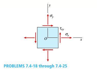
-18 through 7.4-25 An clement in plane stress is subjected to stresses sx,,sy., andtxy(see figure).
Using Mohr’s circle, determine (a) the principal stresses and (b) the maximum shear stresses and associated normal stresses. Show all results on sketches of properly oriented elements.

Expert Solution & Answer
Want to see the full answer?
Check out a sample textbook solution
Students have asked these similar questions
The resistance R and load effect S for a given failure mode are statistically independent random variables
with marginal PDF's
1
fR (r) =
0≤r≤100
100'
fs(s)=0.05e-0.05s
(a) Determine the probability of failure by computing the probability content of the failure domain defined
as {r
Please solve this problem as soon as possible My ID# 016948724
The gears shown in the figure have a diametral pitch of 2 teeth per inch and a 20° pressure angle.
The pinion rotates at 1800 rev/min clockwise and transmits 200 hp through the idler pair to gear
5 on shaft c. What forces do gears 3 and 4 transmit to the idler shaft?
TS
I
y
18T
32T
This
a
12
x
18T
C
48T
5
Chapter 7 Solutions
Mechanics of Materials (MindTap Course List)
Ch. 7 - An clement m plane stress from the frame of a...Ch. 7 - Solve the preceding problem for an element in...Ch. 7 - The stresses on an element are sx= 1000 Psi. sy=...Ch. 7 - .4 The stresses on an clement arc known to be sx=...Ch. 7 - The stresses acting on element A on the web of a...Ch. 7 - Solve the preceding problem if the stresses acting...Ch. 7 - The stresses acting on element B on the web of a...Ch. 7 - An element in plane stress on the fuselage of an...Ch. 7 - The stresses acting on element B (see figure part...Ch. 7 - Solve the preceding problem if the normal and...
Ch. 7 - The polyethylene liner of a settling pond is...Ch. 7 - Solve the preceding problem if the norm al and...Ch. 7 - Two steel rods are welded together (see figure):...Ch. 7 - Repeat the previous problem using ? = 50° and...Ch. 7 - A rectangular plate of dimensions 3.0 in. × 5.0...Ch. 7 - Solve the preceding problem for a plate of...Ch. 7 - A simply supported beam is subjected to point load...Ch. 7 - Repeat the previous problem using sx= 12 MPa.Ch. 7 - At a point on the surface of an elliptical...Ch. 7 - Solve the preceding problem for sx= 11 MPa and...Ch. 7 - An clement m plane stress from the frame of a...Ch. 7 - Solve the preceding problem for the element shown...Ch. 7 - : A gusset plate on a truss bridge is in plane...Ch. 7 - The surface of an airplane wing is subjected to...Ch. 7 - At a point on the web of a girder on an overhead...Ch. 7 - -26 A rectangular plate of dimensions 125 mm × 75...Ch. 7 - -27 A square plate with side dimension of 2 in. is...Ch. 7 - The stresses acting on an element are x= 750 psi,...Ch. 7 - Repeat the preceding problem using sx= 5.5 MPa....Ch. 7 - An element in plane stress is subjected to...Ch. 7 - -4. - An element in plane stress is subjected to...Ch. 7 - An element in plane stress is subjected to...Ch. 7 - The stresses acting on element A in the web of a...Ch. 7 - The normal and shear stresses acting on element A...Ch. 7 - An element in plane stress from the fuselage of an...Ch. 7 - -9The stresses acting on element B in the web of a...Ch. 7 - The normal and shear stresses acting on element B...Ch. 7 - ‘7.3-11 The stresses on an element are sx= -300...Ch. 7 - - 7.3-12 A simply supported beam is subjected to...Ch. 7 - A shear wall in a reinforced concrete building is...Ch. 7 - The state of stress on an element along the...Ch. 7 - -15 Repeat the preceding problem using ??. = - 750...Ch. 7 - A propeller shaft subjected to combined torsion...Ch. 7 - 3-17 The stresses at a point along a beam...Ch. 7 - -18 through 7.3-22 An element in plane stress (see...Ch. 7 - -18 through 7.3-22 An element in plane stress (see...Ch. 7 - -18 through 7.3-22 An element in plane stress (see...Ch. 7 - -18 through 7.3-22 An element in plane stress (see...Ch. 7 - -18 through 7.3-22 An element in plane stress (see...Ch. 7 - At a point on the web of a girder on a gantry...Ch. 7 - The stresses acting on a stress element on the arm...Ch. 7 - The stresses at a point on the down tube of a...Ch. 7 - An element in plane stress on the surface of an...Ch. 7 - A simply supported wood beam is subjected to point...Ch. 7 - A simply supported wood beam is subjected to point...Ch. 7 - Prob. 7.4.1PCh. 7 - .4-2 An element in uniaxial stress is subjected to...Ch. 7 - An element on the gusset plate in Problem 7.2-23...Ch. 7 - An element on the top surface of the fuel tanker...Ch. 7 - An element on the top surface of the fuel tanker...Ch. 7 - An element in biaxial stress is subjected to...Ch. 7 - • - 7.4-7 An element on the surface of a drive...Ch. 7 - - A specimen used in a coupon test has norm al...Ch. 7 - A specimen used in a coupon test is shown in the...Ch. 7 - The rotor shaft of a helicopter (see figure part...Ch. 7 - An element in pure shear is subjected to stresses...Ch. 7 - An clement in plane stress is subjected to...Ch. 7 - Prob. 7.4.13PCh. 7 - An clement in plane stress is subjected to...Ch. 7 - An clement in plane stress is subjected to...Ch. 7 - An clement in plane stress is subjected to...Ch. 7 - Prob. 7.4.17PCh. 7 - -18 through 7.4-25 An clement in plane stress is...Ch. 7 - -18 through 7.4-25 An clement in plane stress is...Ch. 7 - Prob. 7.4.20PCh. 7 - -18 through 7.4-25 An clement in plane stress is...Ch. 7 - Through 7.4-25 An clement in plane stress is...Ch. 7 - -18 through 7.4-25 An clement in plane stress is...Ch. 7 - through 7.4-25 An clement in plane stress is...Ch. 7 - -18 through 7.4-25 An clement in plane stress is...Ch. 7 - 1 A rectangular steel plate with thickness t = 5/8...Ch. 7 - Solve the preceding problem if the thickness of...Ch. 7 - The state of stress on an element of material is...Ch. 7 - An element of a material is subjected to plane...Ch. 7 - Assume that the normal strains x and y , for an...Ch. 7 - A cast-iron plate in biaxial stress is subjected...Ch. 7 - Solve the preceding problem for a steel plate with...Ch. 7 - • - 3 A rectangular plate in biaxial stress (see...Ch. 7 - Solve the preceding problem for an aluminum plate...Ch. 7 - A brass cube of 48 mm on each edge is comp ressed...Ch. 7 - 7.5-11 in. cube of concrete (E = 4.5 X 10⁶ psi. v...Ch. 7 - -12 A square plate of a width h and thickness t is...Ch. 7 - Solve the preceding problem for an aluminum plate...Ch. 7 - A circle of a diameter d = 200 mm is etched on a...Ch. 7 - The normal stress on an elastomeric rubber pad in...Ch. 7 - A rubber sheet in biaxial stress is subjected to...Ch. 7 - An element of aluminum is subjected to tri-axial...Ch. 7 - An element of aluminum is subjected to tri- axial...Ch. 7 - -3 An element of aluminum in the form of a...Ch. 7 - Solve the preceding problem if the element is...Ch. 7 - A cube of cast iron with sides of length a = 4.0...Ch. 7 - Solve the preceding problem if the cube is granite...Ch. 7 - An element of aluminum is subjected to iriaxial...Ch. 7 - Prob. 7.6.8PCh. 7 - A rubber cylinder R of length L and cross-...Ch. 7 - A block R of rubber is confined between plane...Ch. 7 - -11 A rubber cube R of a side L = 3 in. and cross-...Ch. 7 - A copper bar with a square cross section is...Ch. 7 - A solid spherical ball of magnesium alloy (E = 6.5...Ch. 7 - A solid steel sphere (E = 210 GPa, v = 0.3) is...Ch. 7 - Prob. 7.6.15PCh. 7 - An element of material in plain strain has the...Ch. 7 - An clement of material in plain strain has the...Ch. 7 - An element of material in plain strain is...Ch. 7 - An element of material in plain strain is...Ch. 7 - A thin rectangular plate in biaxial stress is...Ch. 7 - Prob. 7.7.6PCh. 7 - A thin square plate in biaxial stress is subjected...Ch. 7 - Prob. 7.7.8PCh. 7 - An clement of material subjected to plane strain...Ch. 7 - Solve the preceding problem for the following...Ch. 7 - The strains for an element of material in plane...Ch. 7 - Solve the preceding problem for the following...Ch. 7 - An clement of material in plane strain (see...Ch. 7 - Solve the preceding problem for the following...Ch. 7 - A brass plate with a modulus of elastici ty E = 16...Ch. 7 - Solve the preceding problem if the plate is made...Ch. 7 - An element in plane stress is subjected to...Ch. 7 - Prob. 7.7.18PCh. 7 - During a test of an airplane wing, the strain gage...Ch. 7 - A strain rosette (see figure) mounted on the...Ch. 7 - A solid circular bar with a diameter of d = 1.25...Ch. 7 - A cantilever beam with a rectangular cross section...Ch. 7 - Solve the preceding problem if the cross-...Ch. 7 - A 600 strain rosette, or delta rosette, consists...Ch. 7 - On the surface of a structural component in a...Ch. 7 - - 7.2-26 The strains on the surface of an...Ch. 7 - Solve Problem 7.7-9 by using Mohr’s circle for...Ch. 7 - 7.7-28 Solve Problem 7.7-10 by using Mohr’s circle...Ch. 7 - Solve Problem 7.7-11 by using Mohr’s circle for...Ch. 7 - Solve Problem 7.7-12 by using Mohr’s circle for...Ch. 7 - Solve Problem 7.7-13 by using Mohr’s circle for...Ch. 7 - Prob. 7.7.32P
Knowledge Booster


Learn more about
Need a deep-dive on the concept behind this application? Look no further. Learn more about this topic, mechanical-engineering and related others by exploring similar questions and additional content below.Similar questions
- Question 1. Draw 3 teeth for the following pinion and gear respectively. The teeth should be drawn near the pressure line so that the teeth from the pinion should mesh those of the gear. Drawing scale (1:1). Either a precise hand drawing or CAD drawing is acceptable. Draw all the trajectories of the involute lines and the circles. Specification: 18tooth pinion and 30tooth gear. Diameter pitch=P=6 teeth /inch. Pressure angle:20°, 1/P for addendum (a) and 1.25/P for dedendum (b). For fillet, c=b-a.arrow_forward5. The figure shows a gear train. There is no friction at the bearings except for the gear tooth forces. The material of the milled gears is steel having a Brinell hardness of 170. The input shaft speed (n2) is 800 rpm. The face width and the contact angle for all gears are 1 in and 20° respectively. In this gear set, the endurance limit (Se) is 15 kpsi and nd (design factor) is 2. (a) Find the revolution speed of gear 5. (b) Determine whether each gear satisfies the design factor of 2.0 for bending fatigue. (c) Determine whether each gear satisfies the design factor of 2.0 for surface fatigue (contact stress). (d) According to the computation results of the questions (b) and (c), explain the possible failure mechanisms for each gear. N4=28 800rpm N₁=43 N5=34 N₂=14 P(diameteral pitch)=8 for all gears Coupled to 2.5hp motorarrow_forward1. The rotating steel shaft is simply supported by bearings at points of B and C, and is driven by a spur gear at D, which has a 6-in pitch diameter. The force F from the drive gear acts at a pressure angle of 20°. The shaft transmits a torque to point A of TA =3000 lbĘ in. The shaft is machined from steel with Sy=60kpsi and Sut=80 kpsi. (1) Draw a shear force diagram and a bending moment diagram by F. According to your analysis, where is the point of interest to evaluate the safety factor among A, B, C, and D? Describe the reason. (Hint: To find F, the torque Tд is generated by the tangential force of F (i.e. Ftangential-Fcos20°) When n=2.5, K=1.8, and K₁ =1.3, determine the diameter of the shaft based on (2) static analysis using DE theory (note that fatigue stress concentration factors need to be used for this question because the loading condition is fatigue) and (3) a fatigue analysis using modified Goodman. Note) A standard diameter is not required for the questions. 10 in Darrow_forward
- 3 N2=28 P(diametral pitch)=8 for all gears Coupled to 25 hp motor N3=34 Full depth spur gears with pressure angle=20° N₂=2000 rpm (1) Compute the circular pitch, the center-to-center distance, and base circle radii. (2) Draw the free body diagram of gear 3 and show all the forces and the torque. (3) In mounting gears, the center-to-center distance was reduced by 0.1 inch. Calculate the new values of center-to-center distance, pressure angle, base circle radii, and pitch circle diameters. (4)What is the new tangential and radial forces for gear 3? (5) Under the new center to center distance, is the contact ratio (mc) increasing or decreasing?arrow_forward2. A flat belt drive consists of two 4-ft diameter cast-iron pulleys spaced 16 ft apart. A power of 60 hp is transmitted by a pulley whose speed is 380 rev/min. Use a service factor (Ks) pf 1.1 and a design factor 1.0. The width of the polyamide A-3 belt is 6 in. Use CD=1. Answer the following questions. (1) What is the total length of the belt according to the given geometry? (2) Find the centrifugal force (Fc) applied to the belt. (3) What is the transmitted torque through the pulley system given 60hp? (4) Using the allowable tension, find the force (F₁) on the tight side. What is the tension at the loose side (F2) and the initial tension (F.)? (5) Using the forces, estimate the developed friction coefficient (f) (6) Based on the forces and the given rotational speed, rate the pulley set. In other words, what is the horse power that can be transmitted by the pulley system? (7) To reduce the applied tension on the tight side, the friction coefficient is increased to 0.75. Find out the…arrow_forwardThe tooth numbers for the gear train illustrated are N₂ = 24, N3 = 18, №4 = 30, №6 = 36, and N₁ = 54. Gear 7 is fixed. If shaft b is turned through 5 revolutions, how many turns will shaft a make? a 5 [6] barrow_forward
- Please do not use any AI tools to solve this question. I need a fully manual, step-by-step solution with clear explanations, as if it were done by a human tutor. No AI-generated responses, please.arrow_forwardPlease do not use any AI tools to solve this question. I need a fully manual, step-by-step solution with clear explanations, as if it were done by a human tutor. No AI-generated responses, please.arrow_forwardCE-112 please solve this problem step by step and give me the correct answerarrow_forward
arrow_back_ios
SEE MORE QUESTIONS
arrow_forward_ios
Recommended textbooks for you
 Mechanics of Materials (MindTap Course List)Mechanical EngineeringISBN:9781337093347Author:Barry J. Goodno, James M. GerePublisher:Cengage Learning
Mechanics of Materials (MindTap Course List)
Mechanical Engineering
ISBN:9781337093347
Author:Barry J. Goodno, James M. Gere
Publisher:Cengage Learning
Understanding Stress Transformation and Mohr's Circle; Author: The Efficient Engineer;https://www.youtube.com/watch?v=_DH3546mSCM;License: Standard youtube license