
Videos
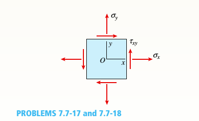
An element in plane stress is subjected to stresses ?? = -8400 psi, ??y = 1100 psi, and
(see figure). The material is aluminum with modulus of elasticity E = 10,000 ksi and Poisson’s ratio v = 0.33.
Determine the following quantities: (a) the strains for an element oriented at an angle 0 = 30°, (b) the principal strains, and (C) the maximum shear strains. Show the results on sketches of properly oriented elements.
(a)
The strains for an element oriented at
Answer to Problem 7.7.17P
The normal strain in x direction is
The normal strain along y direction is
The shear strain is
Explanation of Solution
Given:
Stress along x direction is
Write the Equation for strain along x axis
Here, the normal strain along x direction is
Write the Equation for strain along y axis
Here, the normal strain along the y direction is
Write the expression for the shear strain ix-y plane
Here, modulus of rigidity is
Write the expression for strain along x direction
Write the expression for strain along y direction
Write the expression for shear strain
Here, the shear strain along x-y plane is
Calculation:
Substitute
Substitute
Substitute
Substitute
Substitute
Substitute
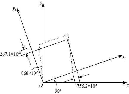
Figure (1)
Conclusion:
The normal strain along x direction is
The normal strain along y direction is
The shear strain along x-y plane is
(b)
The principal strains.
Answer to Problem 7.7.17P
The maximum principal strain is
Explanation of Solution
Write expression for the principal strains.
Here, the maximum principal strain is
Write the expression for the principal angle.
Here,
Calculation:
Substitute
While taking positive sign you get maximum principal stress.
While taking negative sign you get minimum principal stress.
Substitute
In below figure principal strains and principal angle are shown.
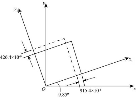 -->
Figure (2)
-->
Figure (2)
Conclusion:
The maximum principal strain is
(c)
The maximum shear strain.
Answer to Problem 7.7.17P
The maximum shear strain is
Explanation of Solution
Write the expression for maximum shear strain,
Here,
Write expression for shear angle
Here,
Write the Equation for average strain
Write expression for maximum shear strain.
Calculation:
Substitute
Substitute
Substitute
Substitute
In below figure average strain and minimum strain are shown.
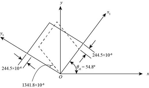
Figure-(3)
Conclusion:
The maximum shear strain is
Want to see more full solutions like this?
Chapter 7 Solutions
Mechanics of Materials (MindTap Course List)


- The evaporator of a vapor compression refrigeration cycle utilizing R-123 as the refrigerant isbeing used to chill water. The evaporator is a shell and tube heat exchanger with the water flowingthrough the tubes. The water enters the heat exchanger at a temperature of 54°F. The approachtemperature difference of the evaporator is 3°R. The evaporating pressure of the refrigeration cycleis 4.8 psia and the condensing pressure is 75 psia. The refrigerant is flowing through the cycle witha flow rate of 18,000 lbm/hr. The R-123 leaves the evaporator as a saturated vapor and leaves thecondenser as a saturated liquid. Determine the following:a. The outlet temperature of the chilled waterb. The volumetric flow rate of the chilled water (gpm)c. The UA product of the evaporator (Btu/h-°F)d. The heat transfer rate between the refrigerant and the water (tons)arrow_forward(Read image) (Answer given)arrow_forwardProblem (17): water flowing in an open channel of a rectangular cross-section with width (b) transitions from a mild slope to a steep slope (i.e., from subcritical to supercritical flow) with normal water depths of (y₁) and (y2), respectively. Given the values of y₁ [m], y₂ [m], and b [m], calculate the discharge in the channel (Q) in [Lit/s]. Givens: y1 = 4.112 m y2 = 0.387 m b = 0.942 m Answers: ( 1 ) 1880.186 lit/s ( 2 ) 4042.945 lit/s ( 3 ) 2553.11 lit/s ( 4 ) 3130.448 lit/sarrow_forward
- Problem (14): A pump is being used to lift water from an underground tank through a pipe of diameter (d) at discharge (Q). The total head loss until the pump entrance can be calculated as (h₁ = K[V²/2g]), h where (V) is the flow velocity in the pipe. The elevation difference between the pump and tank surface is (h). Given the values of h [cm], d [cm], and K [-], calculate the maximum discharge Q [Lit/s] beyond which cavitation would take place at the pump entrance. Assume Turbulent flow conditions. Givens: h = 120.31 cm d = 14.455 cm K = 8.976 Q Answers: (1) 94.917 lit/s (2) 49.048 lit/s ( 3 ) 80.722 lit/s 68.588 lit/s 4arrow_forwardProblem (13): A pump is being used to lift water from the bottom tank to the top tank in a galvanized iron pipe at a discharge (Q). The length and diameter of the pipe section from the bottom tank to the pump are (L₁) and (d₁), respectively. The length and diameter of the pipe section from the pump to the top tank are (L2) and (d2), respectively. Given the values of Q [L/s], L₁ [m], d₁ [m], L₂ [m], d₂ [m], calculate total head loss due to friction (i.e., major loss) in the pipe (hmajor-loss) in [cm]. Givens: L₁,d₁ Pump L₂,d2 오 0.533 lit/s L1 = 6920.729 m d1 = 1.065 m L2 = 70.946 m d2 0.072 m Answers: (1) 3.069 cm (2) 3.914 cm ( 3 ) 2.519 cm ( 4 ) 1.855 cm TABLE 8.1 Equivalent Roughness for New Pipes Pipe Riveted steel Concrete Wood stave Cast iron Galvanized iron Equivalent Roughness, & Feet Millimeters 0.003-0.03 0.9-9.0 0.001-0.01 0.3-3.0 0.0006-0.003 0.18-0.9 0.00085 0.26 0.0005 0.15 0.045 0.000005 0.0015 0.0 (smooth) 0.0 (smooth) Commercial steel or wrought iron 0.00015 Drawn…arrow_forwardThe flow rate is 12.275 Liters/s and the diameter is 6.266 cm.arrow_forward
- An experimental setup is being built to study the flow in a large water main (i.e., a large pipe). The water main is expected to convey a discharge (Qp). The experimental tube will be built at a length scale of 1/20 of the actual water main. After building the experimental setup, the pressure drop per unit length in the model tube (APm/Lm) is measured. Problem (20): Given the value of APm/Lm [kPa/m], and assuming pressure coefficient similitude, calculate the drop in the pressure per unit length of the water main (APP/Lp) in [Pa/m]. Givens: AP M/L m = 590.637 kPa/m meen Answers: ( 1 ) 59.369 Pa/m ( 2 ) 73.83 Pa/m (3) 95.443 Pa/m ( 4 ) 44.444 Pa/m *******arrow_forwardFind the reaction force in y if Ain = 0.169 m^2, Aout = 0.143 m^2, p_in = 0.552 atm, Q = 0.367 m^3/s, α = 31.72 degrees. The pipe is flat on the ground so do not factor in weight of the pipe and fluid.arrow_forwardFind the reaction force in x if Ain = 0.301 m^2, Aout = 0.177 m^2, p_in = 1.338 atm, Q = 0.669 m^3/s, and α = 37.183 degreesarrow_forward
- Problem 5: Three-Force Equilibrium A structural connection at point O is in equilibrium under the action of three forces. • • . Member A applies a force of 9 kN vertically upward along the y-axis. Member B applies an unknown force F at the angle shown. Member C applies an unknown force T along its length at an angle shown. Determine the magnitudes of forces F and T required for equilibrium, assuming 0 = 90° y 9 kN Aarrow_forwardProblem 19: Determine the force in members HG, HE, and DE of the truss, and state if the members are in tension or compression. 4 ft K J I H G B C D E F -3 ft -3 ft 3 ft 3 ft 3 ft- 1500 lb 1500 lb 1500 lb 1500 lb 1500 lbarrow_forwardProblem 14: Determine the reactions at the pin A, and the tension in cord. Neglect the thickness of the beam. F1=26kN F2 13 12 80° -2m 3marrow_forward
 Mechanics of Materials (MindTap Course List)Mechanical EngineeringISBN:9781337093347Author:Barry J. Goodno, James M. GerePublisher:Cengage Learning