Mechanics of Materials (MindTap Course List)
9th Edition
ISBN: 9781337093347
Author: Barry J. Goodno, James M. Gere
Publisher: Cengage Learning
bartleby

Concept explainers

bartleby

Videos

Question
Book Icon
Chapter 7, Problem 7.7.18P

(a)

To determine

The strains for an element oriented at θ=50°.

(a)

Expert Solution
Check Mark

Answer to Problem 7.7.18P

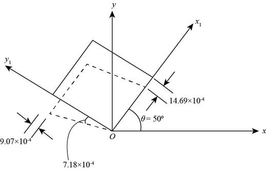
The normal strain in x direction is 14.69×10⁴.

The normal strain along y direction is 9.07×10⁴.

The shear strain is 7.18×10⁴in x-y plane.

Explanation of Solution

Given:

Stress along x direction is 150MPaand stress along y direction is 210MPaand shear stress along x-y plane is 16MPa.

Write the Equation for strain along x axis

εx=1E(σxνσy)(I)

Here, the normal strain along x direction is εx, direct stress along x direction is σxand direct stress along y direction is σyPoissons ratio is νand Young modulus is E.

Write the Equation for strain along y axis

εy=1E(σyνσx)(II)

Here, the normal strain along the y direction is εy.

Write the expression for the shear strain ix-y plane

γxy=2τxy(1+ν)E(III)

Here, modulus of rigidity is Gand the shear strain along x-y plane is γxy.

Write the expression for strain along x direction

εx1=εx+εy2+εxεy2cos2θ+γxy2sin2θ(IV)

Write the expression for strain along y direction

εy1=εx+εyεx1(V)

Write the expression for shear strain

γx1y12=εxεy2sin2θ+γxy2cos2θ(VI)

Here, the shear strain along x-y plane is γxy.

Calculation:

Substitute 150MPafor σx, 210MPafor σyand 0.34for νand 100GPafor Ein Equation (I).

εx=[(150MPa)((0.34)×(210MPa))]100GPa=(150MPa)((0.34)×(210MPa))100GPa(1000MPa1GPa)=1105MPa[(150MPa)((0.34)×(210MPa))]=7.86×10⁴

Substitute 150MPafor σx, 210MPafor σyand 0.34for νan 100GPafor Ein Equation (II).

εy=(210MPa)((0.34)×(150MPa))100GPa=1100GPa(1000MPa1GPa)[(210MPa)((0.34)×(150MPa))]=159MPa105MPa=15.9×10⁴

Substitute 16MPafor τxy, 0.34for νand 100GPafor Ein Equation (III).

γxy=2(16MPa)(1+0.34)100GPa=2(16MPa)(1+0.34)100GPa(1000MPa1GPa)=42.88MPa105MPa=4.29×10⁴

Substitute 7.86×10⁴for εx, 15.9×10⁴for εyand 4.29×10⁴for γxyin Equation (IV).

εx1=((7.86×10415.9×104)2+(7.86×10⁴+15.9×10⁴)2cos(2×(50°))+(4.29×10⁴)2sin(2×(50°)))=(11.88×1040.7×1042.11×104)=14.69×10⁴

Substitute 7.86×10⁴for εx, 15.9×10⁴for εyand 14.69×10⁴for εx1in Equation (V).

εy1=7.86×10415.9×104+14.69×104=23.76×10⁴+14.69×104=9.07×10⁴

Substitute 7.86×10⁴for εx, 15.9×10⁴for εyand 4.29×10⁴for γxyin Equation (VI).

γx1y12=[((7.86×10⁴+15.9×10⁴)2sin(2×50°))+((4.29×1042)cos(2×50°))]γx1y12=3.59×104γx1y1=7.18×10⁴

In below figure the normal strains are shown

:
    Mechanics of Materials (MindTap Course List), Chapter 7, Problem 7.7.18P , additional homework tip  1

    Figure (1)

Conclusion:

The normal strain along x direction is 14.69×10⁴.

The normal strain along y direction is 9.07×10⁴.

The shear strain along x-y plane is 7.18×10⁴.

(b)

To determine

The principal strains.

(b)

Expert Solution
Check Mark

Answer to Problem 7.7.18P

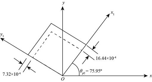
The maximum principal strain is 7.32×10⁴, and the minimum principal strain is 16.44×10⁴.

Explanation of Solution

Write expression for the principal strains.

ε1,2=(εx+εy2)+(εxεy2)2+(γxy2)2(VII)

Here, the maximum principal strain is ε1and the minimum principal strain is ε2.

Write the expression for the principal angle.

tan2θp=γxyεxεy(VIII)

Here, θpis the principal angle.

Calculation:

Substitute 7.86×10⁴for εx, 15.9×10⁴for εyand 4.29×10⁴for γxyin Equation (VII).

ε1,2=((7.86×10415.9×104)2)±((7.86×10⁴+15.9×10⁴)2)2+(4.29×1042)2=11.88×10⁴±(16.16×10⁸)+(4.60×10⁸)=11.88×10⁴±4.556×10⁴

While taking positive sign you get maximum principal strain:

ε1=(11.88+4.556)×104=7.32×10⁴

While taking negative sign you get minimum principal strain.

ε1=(11.884.556)×104=16.44×10⁴

Substitute 7.86×10⁴for εx, 15.9×10⁴for εyand 4.29×10⁴for γxyin Equation (VIII).

tan2θp=4.29×10⁴(7.86×10⁴+15.9×10⁴)tan2θp=0.53358

1802θp=28.1°2θp=151.9°θp=75.95°

In below figure principal strains and principal angle are shown:
    Mechanics of Materials (MindTap Course List), Chapter 7, Problem 7.7.18P , additional homework tip  2

    Figure (2)

Conclusion:

The maximum principal strain is 7.32×10⁴and minimum principal strain is 16.44×10⁴.

(c)

To determine

The maximum shear strain.

(c)

Expert Solution
Check Mark

Answer to Problem 7.7.18P

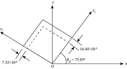
The maximum shear strain is 9.12×10⁴.

Explanation of Solution

Write the expression for maximum shear strain,

γmax2=(εxεy2)2+(γxy2)2(IX)

Here, γmaxis the maximum shear strain.

Write expression for first shear angle

θs1=θp145° (X)

Here, θs1is the first shear angle.

Write expression for second shear angle

θs2=θs145° (XI)

Here, θs2is the second shear angle.

Write the Equation for average strain

εavg=εx+εy2(XII)

Write expression for maximum shear strain.

γmin=γmax (XIII)

Calculation:

Substitute 7.86×10⁴for εx, 15.9×10⁴for εyand 4.29×10⁴for γxyin Equation (IX).

γmax2=((7.86×10⁴+15.9×10⁴)2)2+(4.29×1042)2γmax2=((7.86+15.9)×1042)2+(2.145×10⁴)2γmax2=(4.56×10⁴)γmax=9.12×10⁴

Substitute 165.95°for θp1in Equation (X).

θs1=165.95°45°=120.95°

Substitute 120.95°for θs1in Equation (XI)

θs2=120.95°90°=30.95°

Substitute 7.86×10⁴for εx, 15.9×10⁴for εyin Equation (XII).

εavg=7.86×10415.9×1042=23.76×1042=11.88×10⁴

Substitute 9.12×10⁴for γmax.in Equation (XIII).

γmin=γmax=9.12×10⁴

In below figure average minimum strain and shear angle are shown:
    Mechanics of Materials (MindTap Course List), Chapter 7, Problem 7.7.18P , additional homework tip  3

    Figure (3)

Conclusion:

The maximum shear strain is 9.12×10⁴.

Want to see more full solutions like this?

Subscribe now to access step-by-step solutions to millions of textbook problems written by subject matter experts!
Students have asked these similar questions
The rod length in the figure is L = 28 cm and the profile section is 6x6 cm. Rod pull with a constant force (F = 13000 daN)It has been subjected to stretching. At the end of the pull, the length of the rod increased to 0.030 cm and its width decreased by 0.0014 cm.has been observed. Find out what would be the Poisson's ratio and the Modulus of Elasticity (E) of the bar.
Using this equation FL/AE The assembly consists of two rods (AB and CD) and a rigid bar (AC). A force of 6 kips is applied as shown in the figure. Let AAB = 1.5 in2, ACD = 1.1 in2, LA = 6 ft, LC = 4 ft, a = 1 ft, b = 2 ft and E= 17400 ksi. Determine the deformation in bar CD? Determine the deformation in bar AB? Determine the angle of rotation in rigid bar AC?
Help,please

Chapter 7 Solutions

Mechanics of Materials (MindTap Course List)

Ch. 7 - The polyethylene liner of a settling pond is...Ch. 7 - Solve the preceding problem if the norm al and...Ch. 7 - Two steel rods are welded together (see figure):...Ch. 7 - Repeat the previous problem using ? = 50° and...Ch. 7 - A rectangular plate of dimensions 3.0 in. × 5.0...Ch. 7 - Solve the preceding problem for a plate of...Ch. 7 - A simply supported beam is subjected to point load...Ch. 7 - Repeat the previous problem using sx= 12 MPa.Ch. 7 - At a point on the surface of an elliptical...Ch. 7 - Solve the preceding problem for sx= 11 MPa and...Ch. 7 - An clement m plane stress from the frame of a...Ch. 7 - Solve the preceding problem for the element shown...Ch. 7 - : A gusset plate on a truss bridge is in plane...Ch. 7 - The surface of an airplane wing is subjected to...Ch. 7 - At a point on the web of a girder on an overhead...Ch. 7 - -26 A rectangular plate of dimensions 125 mm × 75...Ch. 7 - -27 A square plate with side dimension of 2 in. is...Ch. 7 - The stresses acting on an element are x= 750 psi,...Ch. 7 - Repeat the preceding problem using sx= 5.5 MPa....Ch. 7 - An element in plane stress is subjected to...Ch. 7 - -4. - An element in plane stress is subjected to...Ch. 7 - An element in plane stress is subjected to...Ch. 7 - The stresses acting on element A in the web of a...Ch. 7 - The normal and shear stresses acting on element A...Ch. 7 - An element in plane stress from the fuselage of an...Ch. 7 - -9The stresses acting on element B in the web of a...Ch. 7 - The normal and shear stresses acting on element B...Ch. 7 - ‘7.3-11 The stresses on an element are sx= -300...Ch. 7 - - 7.3-12 A simply supported beam is subjected to...Ch. 7 - A shear wall in a reinforced concrete building is...Ch. 7 - The state of stress on an element along the...Ch. 7 - -15 Repeat the preceding problem using ??. = - 750...Ch. 7 - A propeller shaft subjected to combined torsion...Ch. 7 - 3-17 The stresses at a point along a beam...Ch. 7 - -18 through 7.3-22 An element in plane stress (see...Ch. 7 - -18 through 7.3-22 An element in plane stress (see...Ch. 7 - -18 through 7.3-22 An element in plane stress (see...Ch. 7 - -18 through 7.3-22 An element in plane stress (see...Ch. 7 - -18 through 7.3-22 An element in plane stress (see...Ch. 7 - At a point on the web of a girder on a gantry...Ch. 7 - The stresses acting on a stress element on the arm...Ch. 7 - The stresses at a point on the down tube of a...Ch. 7 - An element in plane stress on the surface of an...Ch. 7 - A simply supported wood beam is subjected to point...Ch. 7 - A simply supported wood beam is subjected to point...Ch. 7 - Prob. 7.4.1PCh. 7 - .4-2 An element in uniaxial stress is subjected to...Ch. 7 - An element on the gusset plate in Problem 7.2-23...Ch. 7 - An element on the top surface of the fuel tanker...Ch. 7 - An element on the top surface of the fuel tanker...Ch. 7 - An element in biaxial stress is subjected to...Ch. 7 - • - 7.4-7 An element on the surface of a drive...Ch. 7 - - A specimen used in a coupon test has norm al...Ch. 7 - A specimen used in a coupon test is shown in the...Ch. 7 - The rotor shaft of a helicopter (see figure part...Ch. 7 - An element in pure shear is subjected to stresses...Ch. 7 - An clement in plane stress is subjected to...Ch. 7 - Prob. 7.4.13PCh. 7 - An clement in plane stress is subjected to...Ch. 7 - An clement in plane stress is subjected to...Ch. 7 - An clement in plane stress is subjected to...Ch. 7 - Prob. 7.4.17PCh. 7 - -18 through 7.4-25 An clement in plane stress is...Ch. 7 - -18 through 7.4-25 An clement in plane stress is...Ch. 7 - Prob. 7.4.20PCh. 7 - -18 through 7.4-25 An clement in plane stress is...Ch. 7 - Through 7.4-25 An clement in plane stress is...Ch. 7 - -18 through 7.4-25 An clement in plane stress is...Ch. 7 - through 7.4-25 An clement in plane stress is...Ch. 7 - -18 through 7.4-25 An clement in plane stress is...Ch. 7 - 1 A rectangular steel plate with thickness t = 5/8...Ch. 7 - Solve the preceding problem if the thickness of...Ch. 7 - The state of stress on an element of material is...Ch. 7 - An element of a material is subjected to plane...Ch. 7 - Assume that the normal strains x and y , for an...Ch. 7 - A cast-iron plate in biaxial stress is subjected...Ch. 7 - Solve the preceding problem for a steel plate with...Ch. 7 - • - 3 A rectangular plate in biaxial stress (see...Ch. 7 - Solve the preceding problem for an aluminum plate...Ch. 7 - A brass cube of 48 mm on each edge is comp ressed...Ch. 7 - 7.5-11 in. cube of concrete (E = 4.5 X 10⁶ psi. v...Ch. 7 - -12 A square plate of a width h and thickness t is...Ch. 7 - Solve the preceding problem for an aluminum plate...Ch. 7 - A circle of a diameter d = 200 mm is etched on a...Ch. 7 - The normal stress on an elastomeric rubber pad in...Ch. 7 - A rubber sheet in biaxial stress is subjected to...Ch. 7 - An element of aluminum is subjected to tri-axial...Ch. 7 - An element of aluminum is subjected to tri- axial...Ch. 7 - -3 An element of aluminum in the form of a...Ch. 7 - Solve the preceding problem if the element is...Ch. 7 - A cube of cast iron with sides of length a = 4.0...Ch. 7 - Solve the preceding problem if the cube is granite...Ch. 7 - An element of aluminum is subjected to iriaxial...Ch. 7 - Prob. 7.6.8PCh. 7 - A rubber cylinder R of length L and cross-...Ch. 7 - A block R of rubber is confined between plane...Ch. 7 - -11 A rubber cube R of a side L = 3 in. and cross-...Ch. 7 - A copper bar with a square cross section is...Ch. 7 - A solid spherical ball of magnesium alloy (E = 6.5...Ch. 7 - A solid steel sphere (E = 210 GPa, v = 0.3) is...Ch. 7 - Prob. 7.6.15PCh. 7 - An element of material in plain strain has the...Ch. 7 - An clement of material in plain strain has the...Ch. 7 - An element of material in plain strain is...Ch. 7 - An element of material in plain strain is...Ch. 7 - A thin rectangular plate in biaxial stress is...Ch. 7 - Prob. 7.7.6PCh. 7 - A thin square plate in biaxial stress is subjected...Ch. 7 - Prob. 7.7.8PCh. 7 - An clement of material subjected to plane strain...Ch. 7 - Solve the preceding problem for the following...Ch. 7 - The strains for an element of material in plane...Ch. 7 - Solve the preceding problem for the following...Ch. 7 - An clement of material in plane strain (see...Ch. 7 - Solve the preceding problem for the following...Ch. 7 - A brass plate with a modulus of elastici ty E = 16...Ch. 7 - Solve the preceding problem if the plate is made...Ch. 7 - An element in plane stress is subjected to...Ch. 7 - Prob. 7.7.18PCh. 7 - During a test of an airplane wing, the strain gage...Ch. 7 - A strain rosette (see figure) mounted on the...Ch. 7 - A solid circular bar with a diameter of d = 1.25...Ch. 7 - A cantilever beam with a rectangular cross section...Ch. 7 - Solve the preceding problem if the cross-...Ch. 7 - A 600 strain rosette, or delta rosette, consists...Ch. 7 - On the surface of a structural component in a...Ch. 7 - - 7.2-26 The strains on the surface of an...Ch. 7 - Solve Problem 7.7-9 by using Mohr’s circle for...Ch. 7 - 7.7-28 Solve Problem 7.7-10 by using Mohr’s circle...Ch. 7 - Solve Problem 7.7-11 by using Mohr’s circle for...Ch. 7 - Solve Problem 7.7-12 by using Mohr’s circle for...Ch. 7 - Solve Problem 7.7-13 by using Mohr’s circle for...Ch. 7 - Prob. 7.7.32P
Knowledge Booster
Background pattern image
Mechanical Engineering
Learn more about
Need a deep-dive on the concept behind this application? Look no further. Learn more about this topic, mechanical-engineering and related others by exploring similar questions and additional content below.
Similar questions
SEE MORE QUESTIONS
Recommended textbooks for you
Text book image
Mechanics of Materials (MindTap Course List)
Mechanical Engineering
ISBN:9781337093347
Author:Barry J. Goodno, James M. Gere
Publisher:Cengage Learning
Pressure Vessels Introduction; Author: Engineering and Design Solutions;https://www.youtube.com/watch?v=Z1J97IpFc2k;License: Standard youtube license