
Concept explainers
(a)
The tangent elastic modulus.
(a)
Answer to Problem 6.19P
The tangent elastic modulus at zero strain is
Explanation of Solution
Formula Used:
Write the expression for the tangent elastic modulus.
Here,
Calculation:
Refer Figure 6.16 “Tensile stress-strain diagram for four different type of materials” from the book “Material Science and Engineering Properties”.
The value of change is stress for PMMA is
Substitute
Conclusion:
Thus, the tangent elastic modulus at zero strain is
(b)
The yield stress of PMMA.
(b)
Answer to Problem 6.19P
The yield stress for PMMA is
Explanation of Solution
Calculation:
Refer Figure 6.16 “Tensile stress-strain diagram for four different type of materials” from the book “Material Science and Engineering Properties”.
The tensile stress diagram for PMMA is shown in figure below.
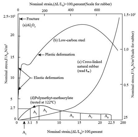
Figure (1)
The value of the yield stress for PMMA is
Conclusion:
Thus, the yield stress for PMMA is
(c)
The resilience of PMMA.
(c)
Answer to Problem 6.19P
The resilience of PMMA is
Explanation of Solution
Formula Used:
Write the expression for the resilience.
Here,
Calculation:
Substitute
Conclusion:
Thus, the resilience of PMMA is
(d)
The ultimate tensile strength of PMMA.
(d)
Answer to Problem 6.19P
The ultimate tensile strength for PMMA is
Explanation of Solution
Calculation:
The ultimate tensile strength in a stress-strain diagram is obtained by observation of the highest point that is reached by the curve after which the necking of curve starts.
Refer Figure 6.16 “Tensile stress-strain diagram for four different type of materials” from the book “Material Science and Engineering Properties”.
The value of the ultimate tensile strength for PMMA is
Conclusion:
Thus, the ultimate tensile strength for PMMA is
(e)
The toughness of PMMA.
(e)
Answer to Problem 6.19P
The toughness of PMMA is
Explanation of Solution
Formula Used:
Write the expression for the first area.
Here,
Write the expression for the second area.
Here,
Write the expression for the third area.
Here,
Write the expression for the fourth area.
Here,
Write the expression for the fifth area.
Here,
Write the expression for the sixth area.
Here,
Write the expression for the toughness of specimen.
Calculation:
Refer Figure 6.16 “Tensile stress-strain diagram for four different type of materials” from the book “Material Science and Engineering Properties”.
The stress strain diagram for PMMA with sub-divided area is shown below,

Figure (2)
Substitute
Substitute
Substitute
Substitute
Substitute
Substitute
Substitute
Conclusion:
Thus, the toughness of PMMA is
Want to see more full solutions like this?
Chapter 6 Solutions
Materials Science And Engineering Properties


- Showing all work and steps find the magnituded and stress ,arrow_forwardWhat is the value of the influence line for the reaction at support A for the beam shown at 5 m to the right of A? Select the reaction at support B to be the redundant. a. 0 kN b. -0.167 kN c. 0.425 kN d. 1.0 kNarrow_forwardDetermine the force in member AB of the truss shown due to a temperature drop of 25°C in Members AB, BC, and CD and a temperature increase of 60°C in member EF. Use the method of consistent deformations. a. 37.34 k b. 0 k c. 28 k d. 46.67 karrow_forward
- What is the approximate axial force in girder EF of the frame shown? Use the portal method. a. 32 kN b. 60 kN c. 12 kN d. 20kNarrow_forwardDetermine the vertical reaction at C for the beam shown and support settlements of 1" at B and ¼" at C. a. 27.0 k b. 28.3 k c. 43.7 k d. 21.0 karrow_forwardWhat is the horizontal reaction component at D for the frame shown? a. 75.00 kN b. 91.67 kN c. 70.31 kN d. 4.69 kNarrow_forward
- Find the vertical reaction at D for the frame shown and a settlement of 50 mm at support D. a. 80.7 kN b. 112.5 kN c. 144.3 kN d. 6.51 kNarrow_forwardDetermine if the W14x 22 beam will safely support a loading of w= 1.5 kip/ft. Theallowable bending stress is oallow = 22 ksi and the allowable shear stress is Tallow = 12 ksi.arrow_forwardWhat is the fixed end moment FEMAB for the beam shown with a settlement of 1.2 in. at support B? a. -102.7 ft-k b. -95.2 ft-k c. -307.7 ft-k d. 279.8 ft-karrow_forward
- Suggest an optimum footing size and shape (minimum area footing), if the vertical loading (includingthe weight of the footing) is 40 kips, and the soil has the following characteristics: c=200 psf, φ=370,and γ=120.0 lb/ft 3. Constraints of the solution are: the maximum dimension of any side of thefooting is 10 ft, and the depth of embedment is between 2 and 4 ft.arrow_forward15.6 A mountain stream flows over a rocky streambed. Apply the Limerinos and Chezy equations to calculate the discharge. The stream has an intermediate rock size d 84 of 30 cm, an average depth of 2.1 m, a slope of S = 0.0037, and a width of 52 m. In SI units, what is the discharge? a. 85, b. 120, c. 160, d. 240, or e. 410.arrow_forwardThe maximum bending moment for the beam shown is positive. a. True b. Falsearrow_forward
 Materials Science And Engineering PropertiesCivil EngineeringISBN:9781111988609Author:Charles GilmorePublisher:Cengage Learning
 Steel Design (Activate Learning with these NEW ti...Civil EngineeringISBN:9781337094740Author:Segui, William T.Publisher:Cengage Learning
 Principles of Foundation Engineering (MindTap Cou...Civil EngineeringISBN:9781337705028Author:Braja M. Das, Nagaratnam SivakuganPublisher:Cengage Learning
 Construction Materials, Methods and Techniques (M...Civil EngineeringISBN:9781305086272Author:William P. Spence, Eva KultermannPublisher:Cengage Learning