
Videos
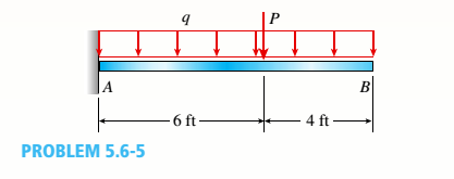
A cantilever beanie B is loaded by a uniform load q and a concentrated load P, as shown in the figure.
- Select the most economical steel C shape from Table F-3(a) in Appendix F; use q = 20 lb/ft and P = 300 lb (assume allowable normal stress is cra= IS ksi).
Note: For parts (a), (b), and (c), revise your initial beam selection as needed to include the distributed weight of the beam in addition to uniform load q.
(a)
The most economical steel
Answer to Problem 5.6.5P
The most economical steel
Explanation of Solution
Given information:
The uniform distributed load is
The following figure shows the free body diagram:
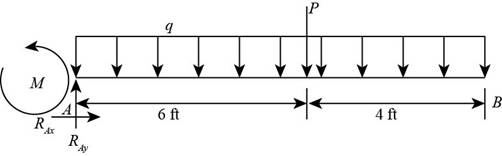
Figure-(1)
Write the expression for the maximum moment of beam.
Here, the load is
Write the expression for the section modulus.
Here, the maximum stress is
Write the expression for the maximum stress.
Here, the maximum stress is
Calculation:
Substitute
Substitute
Refer to the table
Substitute
Substitute
Here, the maximum stress is greater than the calculated stress, so we neglect this section.
Refer to the table
Substitute
Substitute
Hence, from the table “Appendix F” we will use the value
Conclusion:
The most economical steel
(b)
The most economical steel
Answer to Problem 5.6.5P
The most economical steel
Explanation of Solution
Given Information:
The uniform distributed load is
Write the expression for the maximum moment of beam.
Write the expression for the section modulus.
Write the expression for the maximum stress.
Calculation:
Substitute for
Substitute
Refer to the table
Substitute
Substitute
Here, the maximum stress is greater than the calculated stress, so we neglect this section.
Refer to the table
Substitute
Substitute
Hence, from the table “Appendix F” we will use the value
Conclusion:
The maximum value of load
(c)
The most economical steel
Answer to Problem 5.6.5P
The most economical steel
Explanation of Solution
Given Information:
The uniform distributed load is
Write the expression for the maximum moment of beam.
Write the expression for the section modulus.
Write the expression for the maximum stress.
Calculation:
Substitute
Substitute
Refer to the table
Substitute
Substitute
Hence, from the table “Appendix F” we will use the value
Conclusion:
The maximum value of load
Want to see more full solutions like this?
Chapter 5 Solutions
Mechanics of Materials (MindTap Course List)


- 1.7 Find the stress distribution in the beam shown in Fig. 1.23 using two beam elements. A. E. I constant M₂ T + FIGURE 1.23 A fixed-pinned beam subjected to a momentarrow_forward42 PART 1 Introduction A. E. I constant FIGURE 1.22 A fixed-pinned beam. 1.6 Find the stress distribution in the beam shown in Fig. 1.22 using two beam elements.arrow_forward1.4 Using a one-beam element idealization, find the stress distribution under a load of P for the uniform cantilever beam shown in Fig. 1.20. A, E, I constant L FIGURE 1.20 A uniform cantilever beamarrow_forward
- Mechanical engineering,FBD required.arrow_forwardSolve this problem and show all of the workarrow_forwardPlease Please use MATLAB with codes and graph. Recreate the following four Figures of the textbook using MATLAB and the appropriate parameters. Comment on your observations for each Figure. List all of the parameters that you have used. The figure is attached below.arrow_forward
- Please only step 6 (last time I asked it was cut off at that point)arrow_forwardPlease Please use a MATLAB with codes and grap. Recreate the following four Figures of the textbook using MATLAB and the appropriate parameters. Comment on your observations for each Figure. List all of the parameters that you have used. The figure attached below.arrow_forwardI REPEAT!!!!! I NEED HANDDRAWING!!!!! NOT A USELESS EXPLANATION!!!! I REPEAT SUBMIT A HANDDRAWING IF YOU CANNOT UNDERSTAND THIS SKIP IT ! I need the real handdrawing complete it by adding these : Pneumatic Valves Each linear actuator must be controlled by a directional control valve (DCV) (e.g., 5/2 or 4/2 valve). The bi-directional motor requires a reversible valve to change rotation direction. Pressure Regulators & Air Supply Include two pressure regulators as per the assignment requirement. Show the main compressed air supply line connecting all components. Limit Switches & Safety Features Attach limit switches to each actuator to detect positions. Implement a two-handed push-button safety system to control actuator movement. Connections Between Components Draw air supply lines linking the compressor, valves, and actuators. Clearly label all inputs and outputs for better understanding.arrow_forward
- I need the real handdrawing complete it by adding these : Pneumatic Valves Each linear actuator must be controlled by a directional control valve (DCV) (e.g., 5/2 or 4/2 valve). The bi-directional motor requires a reversible valve to change rotation direction. Pressure Regulators & Air Supply Include two pressure regulators as per the assignment requirement. Show the main compressed air supply line connecting all components. Limit Switches & Safety Features Attach limit switches to each actuator to detect positions. Implement a two-handed push-button safety system to control actuator movement. Connections Between Components Draw air supply lines linking the compressor, valves, and actuators. Clearly label all inputs and outputs for better understanding.arrow_forwardAn elastic bar of the length L and cross section area A is rigidly attached to the ceiling of a room, and it supports a mass M. Due to the acceleration of gravity g the rod deforms vertically. The deformation of the rod is measured by the vertical displacement u(x) governed by the following equations: dx (σ(x)) + b(x) = 0 PDE σ(x) = Edx du Hooke's law (1) b(x) = gp= body force per unit volume where E is the constant Young's modulus, p is the density, and σ(x) the axial stress in the rod. g * I u(x) L 2arrow_forwardAn elastic bar of the length L and cross section area A is rigidly attached to the ceiling of a room, and it supports a mass M. Due to the acceleration of gravity g the rod deforms vertically. The deformation of the rod is measured by the vertical displacement u(x) governed by the following equations: dx (σ(x)) + b(x) = 0 PDE σ(x) = Edx du Hooke's law (1) b(x) = gp= body force per unit volume where E is the constant Young's modulus, p is the density, and σ(x) the axial stress in the rod. g * I u(x) L 2arrow_forward
 Mechanics of Materials (MindTap Course List)Mechanical EngineeringISBN:9781337093347Author:Barry J. Goodno, James M. GerePublisher:Cengage Learning