
Mechanics of Materials (MindTap Course List)
9th Edition
ISBN: 9781337093347
Author: Barry J. Goodno, James M. Gere
Publisher: Cengage Learning
expand_more
expand_more
format_list_bulleted
Concept explainers
Videos
Textbook Question
Chapter 5, Problem 5.5.8P
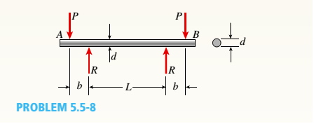
A freight-car axle AS is loaded approximately as shown in the figure, with the forces P representing the car loads (transmitted to the axle through the axle boxes) and the forces R representing the rail loads (transmitted to the axle through the wheels). The diameter of the axle is d = 82 mm, the distance between centers of the rails is Z., and the distance between the forces P and R is A = 220 mm.
Calculate the maximum bending stress vmaxin the axle if P = 50 kN.
Expert Solution & Answer

Trending nowThis is a popular solution!

Students have asked these similar questions
Part 1
The storage tank contains lubricating oil of specific gravity 0.86 In one inclined side of the tank,
there is a 0.48 m diameter circular inspection door, mounted on a horizontal shaft along the centre
line of the gate. The oil level in the tank rests 8.8 m above the mounted shaft. (Please refer table
01 for relevant SG, D and h values).
Describe the hydrostatic force and centre of pressure with the aid of a free body diagram of the
inspection door.
Calculate the magnitude of the hydrostatic force and locate the centre
of pressure.
45°
Estimate the moment that would have to be applied to the shaft to
open the gate.
Stop
B
If the oil level raised by 2 m from the current level, calculate the new
moment required to open the gate.
Figure 01
From thermodynamics
please fill in the table show all work step by step
The 150-lb skater passes point A with a speed of 6 ft/s.
(Figure 1)
Determine his speed when he reaches point B. Neglect friction.
Determine the normal force exerted on him by the track at this point.
25 ft
B
= 4x
A
20 ft
x
Chapter 5 Solutions
Mechanics of Materials (MindTap Course List)
Ch. 5 - A steel wire with a diameter of d = 1/16 in. is...Ch. 5 - A copper wire having a diameter ofd = 4 mm is bent...Ch. 5 - A 4.75-in, outside diameter polyethylene pipe...Ch. 5 - A cantilever beam AB is loaded by a couple M0at...Ch. 5 - A thin strip of steel with a length of L =19 in....Ch. 5 - A bar of rectangular cross section is loaded and...Ch. 5 - A simply supported beam with a length L = 10 ft...Ch. 5 - A cantilever beam is subjected to a concentrated...Ch. 5 - A thin strip of hard copper (E = 16,000 ksi)...Ch. 5 - A steel wire (E = 200 GPa) of a diameter d = L25...
Ch. 5 - A thin, high-strength steel rule (E = 30 x 10ft...Ch. 5 - A simply supported wood beam AB with a span length...Ch. 5 - Beam ABC has simple supports at A and B and an...Ch. 5 - A simply supported beam is subjected to a in early...Ch. 5 - Each girder of the lift bridge (sec figure) is 180...Ch. 5 - A freight-car axle AS is loaded approximately as...Ch. 5 - A seesaw weighing 3 lb/ft of length is occupied by...Ch. 5 - During construction of a highway bridge, the main...Ch. 5 - The horizontal beam ABC of an oil-well pump has...Ch. 5 - A railroad tie (or sleeper) is subjected to two...Ch. 5 - A fiberglass pipe is lifted by a sling, as shown...Ch. 5 - A small dam of height h = 2.0 m is constructed of...Ch. 5 - Determine the maximum tensile stress (7, (due to...Ch. 5 - Determine the maximum bending stress emaxdue to...Ch. 5 - A simple beam A B of a span length L = 24 ft is...Ch. 5 - Determine the maximum tensile stress erand maximum...Ch. 5 - A cantilever beam A3, loaded by a uniform load and...Ch. 5 - A canti lever beam A B of a n isosceles t...Ch. 5 - A cantilever beam, a C12 x 30 section, is...Ch. 5 - A frame ABC travels horizontally with an...Ch. 5 - A beam ABC with an overhang from B to C supports a...Ch. 5 - A cantilever beam AB with a rectangular cross...Ch. 5 - A beam with a T-section is supported and loaded as...Ch. 5 - Consider the compound beam with segments AB and...Ch. 5 - A small dam of a height h = 6 ft is constructed of...Ch. 5 - A foot bridge on a hiking trail is constructed...Ch. 5 - A steel post (E=30×106) having thickness t = 1/8...Ch. 5 - Beam ABCDE has a moment release just right of...Ch. 5 - A simply supported wood beam having a span length...Ch. 5 - A simply supported beam (L = 4.5 m) must support...Ch. 5 - The cross section of a narrow-gage railway bridge...Ch. 5 - A fiberglass bracket A BCD with a solid circular...Ch. 5 - A cantilever beanie B is loaded by a uniform load...Ch. 5 - A simple beam of length L = 5 m carries a uniform...Ch. 5 - A simple beam AB is loaded as shown in the figure....Ch. 5 - A pontoon bridge (see figure) is constructed of...Ch. 5 - A floor system in a small building consists of...Ch. 5 - The wood joists supporting a plank Floor (see...Ch. 5 - A beam ABC with an overhang from B to C is...Ch. 5 - -12 A "trapeze bar" in a hospital room provides a...Ch. 5 - A two-axle carriage that is part of an over head...Ch. 5 - A cantilever beam AB with a circular cross section...Ch. 5 - A propped cantilever beam A BC (see figure) has a...Ch. 5 - A small balcony constructed of wood is supported...Ch. 5 - A beam having a cross section in the form of an un...Ch. 5 - A beam having a cross section in the form of a...Ch. 5 - Determine the ratios of the weights of four beams...Ch. 5 - Prob. 5.6.20PCh. 5 - A steel plate (called a cover ploie) having...Ch. 5 - A steel beam ABC is simply supported at A and...Ch. 5 - A retaining wall 6 ft high is constructed of...Ch. 5 - A retaining wall (Fig. a) is constructed using...Ch. 5 - A beam of square cross section (a = length of each...Ch. 5 - The cross section of a rectangular beam having a...Ch. 5 - A tapered cantilever beam A B of length L has...Ch. 5 - .2 A ligmio.irc ii supported by two vorlical beams...Ch. 5 - Prob. 5.7.3PCh. 5 - Prob. 5.7.4PCh. 5 - Prob. 5.7.5PCh. 5 - A cantilever beam AB with rectangular cross...Ch. 5 - A simple beam ABC having rectangular cross...Ch. 5 - A cantilever beam AB having rectangular cross...Ch. 5 - The shear stresses t in a rectangular beam arc...Ch. 5 - .2 Calculate the maximum shear stress tmaxand the...Ch. 5 - A simply supported wood beam is subjected to...Ch. 5 - A simply supported wood beam with overhang is...Ch. 5 - Two wood beams, each of rectangular cross section...Ch. 5 - A cantilever beam of length L = 2 m supports a...Ch. 5 - A steel beam of length L = 16 in. and...Ch. 5 - A beam of rectangular cross section (width/) and...Ch. 5 - A laminated wood beam on simple supports (figure...Ch. 5 - A laminated plastic beam of square cross section...Ch. 5 - A wood beam AB on simple supports with span length...Ch. 5 - A simply supported wood beam of rectangular cross...Ch. 5 - A square wood platform is 8 ft × 8 ft in area and...Ch. 5 - A wood beam ABC with simple supports at A and B...Ch. 5 - A wood pole with a solid circular cross section (d...Ch. 5 - A simple log bridge in a remote area consists of...Ch. 5 - A vertical pole consisting of a circular tube of...Ch. 5 - A circular pole is subjected to linearly varying...Ch. 5 - A sign for an automobile service station is...Ch. 5 - A steel pipe is subjected to a quadratic...Ch. 5 - -1 through 5.10-6 A wide-flange beam (see figure)...Ch. 5 - -1 through 5.10-6 A wide-flange beam (see figure)...Ch. 5 - -1 through 5.10-6 A wide-flange beam (see figure)...Ch. 5 - -1 through 5.10-6 A wide-flange beam (see figure)...Ch. 5 - -1 through 5.10-6 A wide-flange beam (see figure)...Ch. 5 - -1 through 5.10-6 A wide-flange beam (see figure)...Ch. 5 - A cantilever beam AB of length L = 6.5 ft supports...Ch. 5 - A bridge girder A B on a simple span of length L =...Ch. 5 - A simple beam with an overhang supports a uniform...Ch. 5 - A hollow steel box beam has the rectangular cross...Ch. 5 - A hollow aluminum box beam has the square cross...Ch. 5 - The T-beam shown in the figure has cross-sectional...Ch. 5 - Calculate the maximum shear stress tmax. in the...Ch. 5 - A prefabricated wood I-beam serving as a floor...Ch. 5 - A welded steel gird crhaving the erass section...Ch. 5 - A welded steel girder having the cross section...Ch. 5 - A wood box beam is constructed of two 260 mm × 50...Ch. 5 - A box beam is constructed of four wood boards as...Ch. 5 - Two wood box beams (beams A and B) have the same...Ch. 5 - A hollow wood beam with plywood webs has the...Ch. 5 - A beam of a T cross section is formed by nailing...Ch. 5 - The T-beam shown in the figure is fabricated by...Ch. 5 - A steel beam is built up from a W 410 × 85 wide...Ch. 5 - The three beams shown have approximately the same...Ch. 5 - Two W 310 × 74 Steel wide-flange beams are bolted...Ch. 5 - A pole is fixed at the base and is subjected to a...Ch. 5 - A solid circular pole is subjected to linearly...Ch. 5 - While drilling a hole with a brace and bit, you...Ch. 5 - An aluminum pole for a street light weighs 4600 N...Ch. 5 - A curved bar ABC having a circular axis (radius r...Ch. 5 - A rigid Trame ABC is formed by welding two steel...Ch. 5 - A palm tree weighing 1000 lb is inclined at an...Ch. 5 - A vertical pole of aluminum is fixed at the base...Ch. 5 - Because of foundation settlement, a circular tower...Ch. 5 - A steel bracket of solid circular cross section is...Ch. 5 - A cylindrical brick chimney of height H weighs w =...Ch. 5 - A flying but tress transmit s a load P = 25 kN,...Ch. 5 - A plain concrete wall (i.e., a wall with no steel...Ch. 5 - A circular post, a rectangular post, and a post of...Ch. 5 - Two cables, each carrying a tensile force P = 1200...Ch. 5 - Prob. 5.12.16PCh. 5 - A short column constructed of a W 12 × 35...Ch. 5 - A short column with a wide-flange shape is...Ch. 5 - A tension member constructed of an L inch angle...Ch. 5 - A short length of a C 200 × 17.1 channel is...Ch. 5 - The beams shown in the figure are subjected to...Ch. 5 - The beams shown in the figure are subjected to...Ch. 5 - A rectangular beam with semicircular notches, as...Ch. 5 - A rectangular beam with semicircular notches, as...Ch. 5 - A rectangular beam with notches and a hole (see...
Knowledge Booster


Learn more about
Need a deep-dive on the concept behind this application? Look no further. Learn more about this topic, mechanical-engineering and related others by exploring similar questions and additional content below.Similar questions
- A virtual experiment is designed to determine the effect of friction on the timing and speed of packages being delivered to a conveyor belt and the normal force applied to the tube. A package is held and then let go at the edge of a circular shaped tube of radius R = 5m. The particle at the bottom will transfer to the conveyor belt, as shown below. Run the simulations for μ = 0, 0.1, 0.2, 0.3, 0.4, 0.5, 0.6 and determine the time and speed at which the package is delivered to the conveyor belt. In addition, determine the maximum normal force and its location along the path as measured by angle 0. Submit in hardcopy form: (0) Free Body Diagram, equations underneath, derivations (a) Your MATLAB mfile (b) A table listing the values in 5 columns: μ, T (time of transfer), V (speed of transfer), 0 (angle of max N), Nmax (max N) (c) Based on your results, explain in one sentence what you think will happen to the package if the friction is increased even further, e.g. μ = 0.8. NOTE: The ODE is…arrow_forwardPatm = 1 bar Piston m = 50 kg 5 g of Air T₁ = 600 K P₁ = 3 bar Stops A 9.75 x 10⁻³ m² FIGURE P3.88arrow_forwardAssume a Space Launch System (Figure 1(a)) that is approximated as a cantilever undamped single degree of freedom (SDOF) system with a mass at its free end (Figure 1(b)). The cantilever is assumed to be massless. Assume a wind load that is approximated with a concentrated harmonic forcing function p(t) = posin(ωt) acting on the mass. The known properties of the SDOF and the applied forcing function are given below. • Mass of SDOF: m =120 kip/g • Acceleration of gravity: g = 386 in/sec2 • Bending sectional stiffness of SDOF: EI = 1015 lbf×in2 • Height of SDOF: h = 2000 inches • Amplitude of forcing function: po = 6 kip • Forcing frequency: f = 8 Harrow_forward
- Assume a Space Launch System (Figure 1(a)) that is approximated as a cantilever undamped single degree of freedom (SDOF) system with a mass at its free end (Figure 1(b)). The cantilever is assumed to be massless. Assume a wind load that is approximated with a concentrated harmonic forcing function p(t) = posin(ωt) acting on the mass. The known properties of the SDOF and the applied forcing function are given below. • Mass of SDOF: m =120 kip/g • Acceleration of gravity: g = 386 in/sec2 • Bending sectional stiffness of SDOF: EI = 1015 lbf×in2 • Height of SDOF: h = 2000 inches • Amplitude of forcing function: po = 6 kip • Forcing frequency: f = 8 Hz Figure 1: Single-degree-of-freedom system in Problem 1. Please compute the following considering the steady-state response of the SDOF system. Do not consider the transient response unless it is explicitly stated in the question. (a) The natural circular frequency and the natural period of the SDOF. (10 points) (b) The maximum displacement of…arrow_forwardAssume a Space Launch System (Figure 1(a)) that is approximated as a cantilever undamped single degree of freedom (SDOF) system with a mass at its free end (Figure 1(b)). The cantilever is assumed to be massless. Assume a wind load that is approximated with a concentrated harmonic forcing function p(t) = posin(ωt) acting on the mass. The known properties of the SDOF and the applied forcing function are given below. • Mass of SDOF: m =120 kip/g • Acceleration of gravity: g = 386 in/sec2 • Bending sectional stiffness of SDOF: EI = 1015 lbf×in2 • Height of SDOF: h = 2000 inches • Amplitude of forcing function: po = 6 kip • Forcing frequency: f = 8 Hz Figure 1: Single-degree-of-freedom system in Problem 1. Please compute the following considering the steady-state response of the SDOF system. Do not consider the transient response unless it is explicitly stated in the question. (a) The natural circular frequency and the natural period of the SDOF. (10 points) (b) The maximum displacement of…arrow_forwardPlease solve 13 * √(2675.16)² + (63.72 + 2255,03)² = 175x106 can you explain the process for getting d seperate thank youarrow_forward
- If the 300-kg drum has a center of mass at point G, determine the horizontal and vertical components of force acting at pin A and the reactions on the smooth pads C and D. The grip at B on member DAB resists both horizontal and vertical components of force at the rim of the drum. P 60 mm; 60 mm: 600 mm A E 30° B C 390 mm 100 mm D Garrow_forwardThe design of the gear-and-shaft system shown requires that steel shafts of the same diameter be used for both AB and CD. It is further required that the angle D through which end D of shaft CD rotates not exceed 1.5°. Knowing that G = 77.2 GPa, determine the required diameter of the shafts. 40 mm 400 mm 100 mm 600 mm T-1000 N-m Darrow_forwardAssume a Space Launch System (Figure 1(a)) that is approximated as a cantilever undamped single degree of freedom (SDOF) system with a mass at its free end (Figure 1(b)). The cantilever is assumed to be massless. Assume a wind load that is approximated with a concentrated harmonic forcing function p(t) = posin(ωt) acting on the mass. The known properties of the SDOF and the applied forcing function are given below. • Mass of SDOF: m =120 kip/g • Acceleration of gravity: g = 386 in/sec2 • Bending sectional stiffness of SDOF: EI = 1015 lbf×in2 • Height of SDOF: h = 2000 inches • Amplitude of forcing function: po = 6 kip • Forcing frequency: f = 8 Hzarrow_forward
- 13.44 The end of a cylindrical liquid cryogenic propellant tank in free space is to be protected from external (solar) radiation by placing a thin metallic shield in front of the tank. Assume the view factor Fts between the tank and the shield is unity; all surfaces are diffuse and gray, and the surroundings are at 0 K. Tank T₁ Shield, T T₁ = 100 K E1 Solar irradiation Gs ε₁ = ε₂ = 0.05 ε₁ = 0.10 Gs = 1250 W/m² E2 Find the temperature of the shield T, and the heat flux (W/m²) to the end of the tank.arrow_forwardquestion 664 thank youarrow_forward13.38 Consider the attic of a home located in a hot climate. The floor of the attic is characterized by a width of L₁ = 8 m while the roof makes an angle of 0 = 30° from the horizontal direction, as shown in the schematic. The homeowner wishes to reduce the heat load to the home by adhering bright aluminum foil (ε = 0.07) onto the surfaces of the attic space. Prior to installation of the foil, the surfaces are of emissivity & = 0.90. Attic A2, 82, T2 0 = 30° A1, E1, T₁ 土 L₁ = 8 m (a) Consider installation on the bottom of the attic roof only. Determine the ratio of the radiation heat transfer after to before the installation of the foil. (b) Determine the ratio of the radiation heat transfer after to before installation if the foil is installed only on the top of the attic floor. (c) Determine the ratio of the radiation heat transfer if the foil is installed on both the roof bottom and the floor top.arrow_forward
arrow_back_ios
SEE MORE QUESTIONS
arrow_forward_ios
Recommended textbooks for you
 Mechanics of Materials (MindTap Course List)Mechanical EngineeringISBN:9781337093347Author:Barry J. Goodno, James M. GerePublisher:Cengage Learning
Mechanics of Materials (MindTap Course List)
Mechanical Engineering
ISBN:9781337093347
Author:Barry J. Goodno, James M. Gere
Publisher:Cengage Learning
Everything About COMBINED LOADING in 10 Minutes! Mechanics of Materials; Author: Less Boring Lectures;https://www.youtube.com/watch?v=N-PlI900hSg;License: Standard youtube license