
Videos
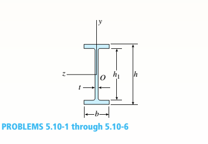
-1 through 5.10-6 A wide-flange beam (see figure) is subjected to a shear force V. Using the dimensions of the cross section, calculate the moment of inertia and then determine the following quantities:
- The maximum shear stress tinixin the web.
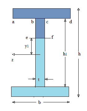
Note: Disregard the fillets at the junctions of the web and flanges and determine all quantities, including the moment of inertia, by considering the cross section to consist of three rectangles.
5.10-2 Dimensions of cross section: b = 180 mm, v = 12 mm, h = 420 mm,
i = 380 mm, and V = 125 kN.
(a).
To Find:
The moment of inertia and the maximum shear stress in the web.
Answer to Problem 5.10.2P
The maximum shear stress in the web is =
Explanation of Solution
Given Information:
Shear Force
Dimensions:
Concept Used:
Following formula will be used:
Maximum shear stress,
Moment of inertia of rectangle,
Calculation:
Area of upper and lower flanges/rectangles:

Second rectangle is
In which
The first moment of areas of
By putting the values of
The moment of inertia for the I section is given by following formula:
The maximum value of shear stress will be at neutral axis when
Conclusion:
The maximum shear stress in the web is
(b).
To Find:
The minimum shear stress in web.
Answer to Problem 5.10.2P
The minimum shear stress in the web is
Explanation of Solution
Given Information:
Shear Force
Dimensions,
Concept Used:
Following formula will be used:
Minimum shear stress,
Calculation:
Area of upper and lower flanges:
Second rectangle is
In which
The first moment of areas of
By putting the values of
The moment of inertia for the I section is given by following formula:
The minimum value of shear stress will be at
Conclusion:
The minimum shear stress in the web is
(c).
To Find:
The average shear stress in the web.
Answer to Problem 5.10.2P
The average shear stress in the web is
Explanation of Solution
Given Information:
Shear Force
Dimensions:
Concept Used:
Following formula will be used:
Average shear stress,
Calculation:
The average shear stress in the web is:
Conclusion:
The average shear stress in the web is
(d).
To Find:
Shear force
Answer to Problem 5.10.2P
Shear force in the web is
Explanation of Solution
Given Information:
Shear Force
Dimensions,
Concept Used:
Following formula will be used
Shear stress in the web,
Calculation:
Shear stress in the web:
Conclusion:
Shear force in the web is
Want to see more full solutions like this?
Chapter 5 Solutions
Mechanics of Materials (MindTap Course List)


- practise questionarrow_forwardCan you provide steps and an explaination on how the height value to calculate the Pressure at point B is (-5-3.5) and the solution is 86.4kPa.arrow_forwardPROBLEM 3.46 The solid cylindrical rod BC of length L = 600 mm is attached to the rigid lever AB of length a = 380 mm and to the support at C. When a 500 N force P is applied at A, design specifications require that the displacement of A not exceed 25 mm when a 500 N force P is applied at A For the material indicated determine the required diameter of the rod. Aluminium: Tall = 65 MPa, G = 27 GPa. Aarrow_forward
- Find the equivalent mass of the rocker arm assembly with respect to the x coordinate. k₁ mi m2 k₁arrow_forward2. Figure below shows a U-tube manometer open at both ends and containing a column of liquid mercury of length l and specific weight y. Considering a small displacement x of the manometer meniscus from its equilibrium position (or datum), determine the equivalent spring constant associated with the restoring force. Datum Area, Aarrow_forward1. The consequences of a head-on collision of two automobiles can be studied by considering the impact of the automobile on a barrier, as shown in figure below. Construct a mathematical model (i.e., draw the diagram) by considering the masses of the automobile body, engine, transmission, and suspension and the elasticity of the bumpers, radiator, sheet metal body, driveline, and engine mounts.arrow_forward
- 3.) 15.40 – Collar B moves up at constant velocity vB = 1.5 m/s. Rod AB has length = 1.2 m. The incline is at angle = 25°. Compute an expression for the angular velocity of rod AB, ė and the velocity of end A of the rod (✓✓) as a function of v₂,1,0,0. Then compute numerical answers for ȧ & y_ with 0 = 50°.arrow_forward2.) 15.12 The assembly shown consists of the straight rod ABC which passes through and is welded to the grectangular plate DEFH. The assembly rotates about the axis AC with a constant angular velocity of 9 rad/s. Knowing that the motion when viewed from C is counterclockwise, determine the velocity and acceleration of corner F.arrow_forward500 Q3: The attachment shown in Fig.3 is made of 1040 HR. The static force is 30 kN. Specify the weldment (give the pattern, electrode number, type of weld, length of weld, and leg size). Fig. 3 All dimension in mm 30 kN 100 (10 Marks)arrow_forward
- (read image) (answer given)arrow_forwardA cylinder and a disk are used as pulleys, as shown in the figure. Using the data given in the figure, if a body of mass m = 3 kg is released from rest after falling a height h 1.5 m, find: a) The velocity of the body. b) The angular velocity of the disk. c) The number of revolutions the cylinder has made. T₁ F Rd = 0.2 m md = 2 kg T T₂1 Rc = 0.4 m mc = 5 kg ☐ m = 3 kgarrow_forward(read image) (answer given)arrow_forward
 Mechanics of Materials (MindTap Course List)Mechanical EngineeringISBN:9781337093347Author:Barry J. Goodno, James M. GerePublisher:Cengage Learning