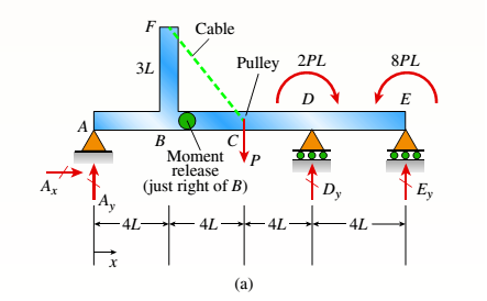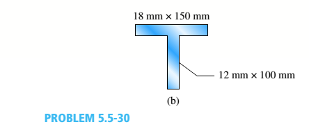
Beam ABCDE has a moment release just right of joint B and has concentrated moment loads at D and E. In addition, a cable with tension P is attached at fand runs over a pulley at C (Fig, a). The beam is constructed using two steel plates, which arc welded to form a T cross section (see Fig. b). Consider ßexuralstresses only Find the maximum permissible value of load variable P if the allowable bending stress is 130 M Pa. Ignore the self-weight of the frame members and let length variable L = 0.75 m.


The maximum permissible load.
Answer to Problem 5.5.30P
The maximum permissible load is
Explanation of Solution
Given information:
The allowable bending stress is
Write the expression for the force equilibrium in x direction.
Here, the reaction at point
Write the expression for the moment at the point of release.
Here, the length of the beam is
Write the expression for the moment about point
Here, the vertical reaction at point
Write the expression for the force equilibrium in y direction.
Here, the vertical reaction at point
Write the expression for the moment at
Here the moment is
Write the expression for the moment at
Write the expression for the moment at
Write the expression for the moment at other points.
Write the expression for the area of the
Here, the width of the flange is
Write the expression for the centroid.
Here, the distance of the centroid from one end is
Write the expression for the other distance of the centroid.
Here, the distance of the centroid from other end is
Write the expression for the moment of inertia about z axis.
Here, the moment of inertia about z axis is
Write the expression for the section modulus at the top section.
Here, the section modulus at top section is
Here, the section modulus of top section is
Write the expression for the section modulus at the bottom section.
Here, the section modulus of bottom section is
Write the expression for the maximum permissible load.
Here, the allowable stress is
Calculation:
Substitute
Substitute
Substitute
Substitute
Substitute
Substitute
Substitute
Substitute
Substitute
Conclusion:
The maximum permissible load is
Want to see more full solutions like this?
Chapter 5 Solutions
Mechanics of Materials (MindTap Course List)
- An Inclining experiment done on a ship thats 6500 t, a mass of 30t was moved 6.0 m transvesly causing a 30 cm deflection in a 6m pendulum, calculate the transverse meta centre height.arrow_forwarda ship 150 m long and 20.5 m beam floats at a draught of8 m and displaces 19 500 tonne. The TPC is 26.5 and midshipsection area coefficient 0.94. Calculate the block, prismatic andwaterplane area coefficients.arrow_forwardA vessel loads 680 t fuel between forward and aft deep tanks. centre of gravity of forward tank is 24m forward of ships COG. centre to centre between tanks is 42 m. how much in each tank to keep trim the samearrow_forward
- Beam of a vessel is 11% its length. Cw =0.72. When floating in SW of relative denisity 1.03, TPC is 0.35t greater than in freshwater. Find the length of the shiparrow_forwardAn inclining experiment was carried out on a ship of 4000tonne displacement, when masses of 6 tonne were moved transverselythrough 13.5 m. The deflections of a 7.5 m pendulurnwere 81, 78, 85, 83, 79, 82, 84 and 80 mm respectively.Caiculate the metacentric height.arrow_forwardA ship of 10 000 tonne displacement has a waterplanearea of 1300 m2. The ship loads in water of 1.010 t/m3 andmoves into water of 1.026 t/m3. Find the change in meandraughtarrow_forward
- A ship of 7000 tonne displacement has a waterplane areaof 1500 m2. In passing from sea water into river water of1005 kg/m3 there is an increase in draught of 10 cm. Find the Idensity of the sea water.arrow_forwardA ship has 300 tonne of cargo in the hold, 24 m forward ofmidships. The displacement of the vessel is 6000 tonne and its centre of gravity is 1.2 m forward of midships.Find the new position of the centre of gravity if this cargo ismoved to an after hold, 40 m from midshipsarrow_forwardSketch and describe how ships are supported in dry dock. When and where does the greatest amount of stresses occur?arrow_forward
- Sketch and desribe a balanced rudder and how it is suspendedarrow_forwardA ship 140 m long and 18 m beam floats at a draught of9 m. The immersed cross-sectionai areas at equai intervais are 5,60, 116, 145, 152, 153, 153, 151, 142, 85 and 0 m2 respectively.Calculate:(a) displacement(b) block coefficient(c) midship section area coefficient(d) prismatic coefficient.arrow_forwardA steamer has waterplane area 1680m2 recorded in water with relative denisty 1.013. Displacement = 1200 t, calculate difference in draught in salwater reltive denisity 1.025.arrow_forward
 Mechanics of Materials (MindTap Course List)Mechanical EngineeringISBN:9781337093347Author:Barry J. Goodno, James M. GerePublisher:Cengage Learning
