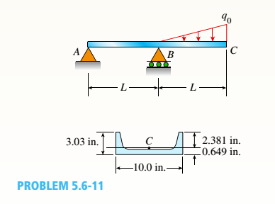
A beam ABC with an overhang from B to C is constructed of a C 10 × 30 channel section with flanges facing upward (sec figure). The beam supports its own weight (30 lb/ft) plus a triangular load of maximum intensity g0 acting on the overhang. The allowable stresses in tension and compression arc IS ksi and 12 ksi, respectively.
- Determine the allowable triangular load intensity allow if tne distance L equals 4 ft.

(a)
The allowable triangular load intensity.
Answer to Problem 5.6.11P
The allowable triangular load intensity is
Explanation of Solution
Given information:
The weight of the beam is
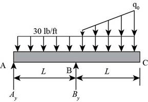
The following figure shows the free body diagram.

Figure-(1)
Write the expression for the moment about point
Here, the vertical reaction on point
Write the expression for the equilibrium forces at point
Here, the vertical reaction on point
Write the expression for the maximum moment at point
Here, the maximum moment is
Write the expression for the allowable bending moment based on tension.
Here, maximum tensile stress is
Write the expression for the allowable bending moment based on compression.
Here, maximum compressible stress is
Write the expression for the load intensity of triangular load considering tension.
Write the expression for the load intensity of triangular load considering compression.
Calculation:
Substitute
Substitute
Substitute
Substitute
Substitute
Substitute
Conclusion:
The allowable triangular load intensity is
(b)
The allowable triangular load intensity when the beam is rotated
Answer to Problem 5.6.11P
The allowable triangular load intensity when the beam is rotated
Explanation of Solution
Write the expression for the allowable bending moment based on tension.
Write the expression for the allowable bending moment based on compression.
Write the expression for the load intensity of triangular load considering tension.
Write the expression for the load intensity of triangular load considering compression.
Calculation:
Substitute
Substitute
Substitute
Substitute
Conclusion:
The allowable triangular load intensity when the beam is rotated
Want to see more full solutions like this?
Chapter 5 Solutions
Mechanics of Materials (MindTap Course List)
- +1. 0,63 fin r= 0.051 P The stepped rod in sketch is subjected to a tensile force that varies between 4000 and 7000 lb. The rod has a machined surface finish everywhere except the shoulder area, where a grinding operation has been performed to improve the fatigue resistance of the rod. Using a 99% probability of survival, determine the safety factor for infinite life if the rod is made of AISI 1080 steel, quenched and tempered at 800°c Use the Goodman line. Does the part fail at the fillet? Explainarrow_forwardSolve this problem and show all of the workarrow_forwardSolve this problem and show all of the workarrow_forward
- Qu. 17 Compute linear density values for [100] for silver (Ag). Express your answer in nm''. . Round off the answer to three significant figures. Qu. 18 Compute linear density value for [111] direction for silver (Ag). Express your answer in nm'. Round off the answer to three significant figures. Qu. 19 Compute planar density value for (100) plane for chromium (Cr). Express your answer in nm?. Round off the answer to two significant figures. Qu. 20 Compute planar density value for (110) plane for chromium (Cr). Express your answer in nm ≥ to four significant figures. show all work please in material engineeringarrow_forward3-142arrow_forwardI need solutionsarrow_forward
- 3-137arrow_forwardLarge wind turbines with a power capacity of 8 MW and blade span diameters of over 160 m areavailable for electric power generation. Consider a wind turbine with a blade span diameter of 120m installed at a site subjected to steady winds at 8.25 m/s. Taking the overall efficiency of thewind turbine to be 33 percent and the air density to be 1.25 kg/m3, determine the electric powergenerated by this wind turbine. Also, assuming steady winds of 8.25 m/s during a 24-h period,determine the amount of electric energy and the revenue generated per day for a unit price of$0.08/kWh for electricity.arrow_forwardThe basic barometer can be used to measure the height of a building. If the barometric readingsat the top and at the bottom of a building are 672 and 696 mmHg, respectively, determine theheight of the building. Take the densities of air and mercury to be 1.18 kg/m3 and 13,600 kg/m3,respectivelyarrow_forward
 Mechanics of Materials (MindTap Course List)Mechanical EngineeringISBN:9781337093347Author:Barry J. Goodno, James M. GerePublisher:Cengage Learning
