
Concept explainers
Videos
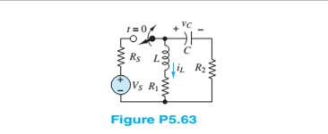
If the switch shown in Figure P5.63 is closed at
determine the current
Want to see the full answer?
Check out a sample textbook solution
Chapter 5 Solutions
Principles and Applications of Electrical Engineering


- a single circuit 50hz transmission line is 362 km long. the load is125mw at 200kv with 100% power factor. 1. evaluate the incident and reflected voltages at the receiving end of the line and at the sending end of the line. 2. determine the line voltage at the sending end from the incident and reflected voltages. 3. computer the wavelength and velocity of propagation. parameters of the line are r = 0.1069 ohms/km. l=1.355mh/km c=8.452nf/km g=0arrow_forwardQ1. Figure 1 shows a differential amplifier. Assume that all transistors are identical. ẞ=180, V = 0.026 Vand V = 0.7V. a) b) Show that the d.c. bias current to the differential pairs is Iccs = 0.6 mA. Calculate the d.c. voltages at the output terminals V。1 and V02- c) Given that the input signals are v₁ = 4 sin(wt) and V₁₂ = 2sin(wt) in mV, find the a.c. voltage between V01 and V02-arrow_forwardQ1. Figure 1 shows a differential amplifier. Assume that all transistors are identical. ẞ=180, V = 0.026 Vand V = 0.7V. a) b) Show that the d.c. bias current to the differential pairs is Iccs = 0.6 mA. Calculate the d.c. voltages at the output terminals V。1 and V02- c) Given that the input signals are v₁ = 4 sin(wt) and V₁₂ = 2sin(wt) in mV, find the a.c. voltage between V01 and V02-arrow_forward
- Q4 Determine the Y-parameters at a frequency of 10 kHz for the two-port network shown in figure below. Present your answer in matrix form. R1 R3 C3 R5 L5 •w• 5 Ohm ww 4 Ohm 200 μF 5 Ohm 8.4 mH 1 Ohm R2 C4 796 µF 400 μF C2arrow_forwardQ1. Figure 1 shows (a) a differential amplifier and (b) a current mirror. All transistors in the circuit are identical and their parameters are: VBE = 0.7 V, VT = 0.026 V, and ẞ = 150. a) Given that the biasing current of Figure 1(a) is I = 1 mA, determine the dc voltages at the output terminals of the differential amplifier. b) Given that the biasing current of Figure 1(a) is I = 1 mA and the ac input signal is via = 1.5 sin(wt) mv, find the corresponding ac output voltage at terminal vo₁ of the differential amplifier. c) In order to provide an output current of 1 mA using on Figure 1(b), find the value for the resistor, R, in Figure 1(b).arrow_forwardQ2. Two op-amp circuits are shown in Figure 2. One of them is an inverting amplifier and the other is a Schmitt trigger. Assume the op-amps used in both circuits are ideal op-amps. The output of the Schmitt trigger is switching between -12 V and +12V (i.e., Vmax = ±12 V). a) Identify which is the inverting amplifier and which is the Schmitt trigger. b) Use the corresponding circuit diagram in Figure 2 to design an inverting amplifier that has a gain of -20 with the output offset voltage minimised. Determine the values of the resistors. c) Select the corresponding circuit diagram in Figure 2 to design a Schmitt trigger that has a lower trigger level of -1 V and an upper trigger level of +2 V. Determine the values of resistors. Sketch the transfer characteristics of this trigger.arrow_forward
- Q2. A simple comparator and a Schmitt trigger are shown in Figures 2(a) and 2(b). The maximum output voltage, Vmax, can switch between -10 V and +10 V for both circuits. The lower and upper trigger levels of the Schmitt trigger are -1 V and +2 V, respectively. a) Based on the information given above, sketch the transfer characteristics for both circuits. b) Show that the hysteresis of the Schmitt trigger of Figure 2(b) can be expressed as 2. R₁- Vmax Vnys R₁ + R₂ c) Using the parameters provided above, determine the ratio of R₂/R₁ for the circuit of Figure 2(b).arrow_forwardDon't use ai to answer I will report you answerarrow_forward3 phase transformer bank is connected with the primaries in deltas and secondaries in wye. Line voltage of the primary is 120V and secondary side is 240V. Required to find the ratio of primary to secondary turns on each of the single phase transformers.arrow_forward
- A generator delivers power through a transmission line to a star-connected load. The system is balanced. Find the values of the currents involved in per unit, considering: (a) single-phase bases and (b) three-phase bases. Datos: S₁ = 2 MVA Vg = 13.2 kV Generador ++ Linea Demanda Pg+jQg Uga ZLT a Zlinea 8.68+j3.162 Zcarga = 70+/10 la ZDa ZD b ZD€ Bases trifásicas: Ug b ZLT b Sb36 = 2 MVA Vb34 = 13.820° kV Ugo ZLTCarrow_forwardcontrol systemarrow_forwardcontrol systemarrow_forward
 Introductory Circuit Analysis (13th Edition)Electrical EngineeringISBN:9780133923605Author:Robert L. BoylestadPublisher:PEARSON
 Delmar's Standard Textbook Of ElectricityElectrical EngineeringISBN:9781337900348Author:Stephen L. HermanPublisher:Cengage Learning
 Programmable Logic ControllersElectrical EngineeringISBN:9780073373843Author:Frank D. PetruzellaPublisher:McGraw-Hill Education
 Fundamentals of Electric CircuitsElectrical EngineeringISBN:9780078028229Author:Charles K Alexander, Matthew SadikuPublisher:McGraw-Hill Education
 Electric Circuits. (11th Edition)Electrical EngineeringISBN:9780134746968Author:James W. Nilsson, Susan RiedelPublisher:PEARSON
 Engineering ElectromagneticsElectrical EngineeringISBN:9780078028151Author:Hayt, William H. (william Hart), Jr, BUCK, John A.Publisher:Mcgraw-hill Education,