
Principles and Applications of Electrical Engineering
6th Edition
ISBN: 9780073529592
Author: Giorgio Rizzoni Professor of Mechanical Engineering, James A. Kearns Dr.
Publisher: McGraw-Hill Education
expand_more
expand_more
format_list_bulleted
Videos
Textbook Question
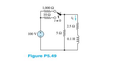
Chapter 5, Problem 5.49HP
In the circuit in Figure P5.49, how long after the switch is thrown at
Expert Solution & Answer

Trending nowThis is a popular solution!

Students have asked these similar questions
I need help with this problem and an explanation of the solution for the image described below. (Introduction to Signals and Systems)
I hope the solution is on paper and not
artificial intelligence.
The subject is control system
I hope the solution is on paper and not artificial intelligence.
Chapter 5 Solutions
Principles and Applications of Electrical Engineering
Ch. 5 - Write the differential equations fort t0 for iL...Ch. 5 - Write the differential equation fort t0 for vc in...Ch. 5 - Write the differential equation fort t0 for iC in...Ch. 5 - Write the differential equation for t0 for iL in...Ch. 5 - Write the differential equation for t0 for vc in...Ch. 5 - Write the differential equations for t0 for iC and...Ch. 5 - Prob. 5.7HPCh. 5 - Write the differential equation for t0 for iC in...Ch. 5 - Write the differential equation for t0 for iL in...Ch. 5 - Write the differential equations for: t0 for iL...
Ch. 5 - Determine the initial and final conditions on iL...Ch. 5 - Determine the initial and final conditions on vc...Ch. 5 - Determine the initial and final conditions on iC...Ch. 5 - Determine the initial and final conditions on iL...Ch. 5 - Determine the initial and final conditions on vc...Ch. 5 - Determine the initial and final conditions on iC...Ch. 5 - Determine the initial and final conditions on vC...Ch. 5 - Prob. 5.18HPCh. 5 - Prob. 5.19HPCh. 5 - Determine the initial and final conditions on iL...Ch. 5 - At t=0 , just before the switch is opened, the...Ch. 5 - Prob. 5.22HPCh. 5 - Determine the current ic through the capacitor...Ch. 5 - Prob. 5.24HPCh. 5 - Prob. 5.25HPCh. 5 - Assume that steady-state conditions exist in...Ch. 5 - Assume that steady-state conditions exist in the...Ch. 5 - Prob. 5.28HPCh. 5 - Assume that steady-state conditions exist in the...Ch. 5 - Find the Thévenin equivalent network seen by the...Ch. 5 - Prob. 5.31HPCh. 5 - Prob. 5.32HPCh. 5 - Prob. 5.33HPCh. 5 - For t0 , the circuit shown in Figure P5.34 is at...Ch. 5 - The circuit in Figure P5.35 is a simple model of...Ch. 5 - Prob. 5.36HPCh. 5 - Determine the current iC through the capacitor in...Ch. 5 - Determine the voltage vL across the inductor in...Ch. 5 - Prob. 5.39HPCh. 5 - For t0 , the circuit shown in Figure P5.39 is at...Ch. 5 - Prob. 5.41HPCh. 5 - Prob. 5.42HPCh. 5 - Prob. 5.43HPCh. 5 - Prob. 5.44HPCh. 5 - For the circuit shown in Figure P5.41, assume that...Ch. 5 - Prob. 5.46HPCh. 5 - Prob. 5.47HPCh. 5 - For the circuit in Figure P5.47, assume...Ch. 5 - In the circuit in Figure P5.49, how long after the...Ch. 5 - Refer to Figure P5.49 and assume that the switch...Ch. 5 - The circuit in Figure P5.51 includes a...Ch. 5 - At t=0 the switch in the circuit in Figure...Ch. 5 - Prob. 5.53HPCh. 5 - The analogy between electrical and thermal systems...Ch. 5 - The burner and pot of Problem 5.54 can be modeled...Ch. 5 - Prob. 5.56HPCh. 5 - Prob. 5.57HPCh. 5 - Prob. 5.58HPCh. 5 - The circuit in Figure P5.59 models the charging...Ch. 5 - Prob. 5.60HPCh. 5 - In the circuit shown in Figure P5.61:...Ch. 5 - Prob. 5.62HPCh. 5 - If the switch shown in Figure P5.63 is closed at...Ch. 5 - Prob. 5.64HPCh. 5 - Prob. 5.65HPCh. 5 - Prob. 5.66HPCh. 5 - Prob. 5.67HPCh. 5 - Prob. 5.68HPCh. 5 - Assume the switch in the circuit in Figure...Ch. 5 - Prob. 5.70HPCh. 5 - Prob. 5.71HPCh. 5 - Prob. 5.72HPCh. 5 - Prob. 5.73HPCh. 5 - Prob. 5.74HPCh. 5 - Prob. 5.75HPCh. 5 - Prob. 5.76HPCh. 5 - Prob. 5.77HPCh. 5 - Prob. 5.78HPCh. 5 - Prob. 5.79HPCh. 5 - Assume the circuit in Figure P5.80 is in DC steady...Ch. 5 - Prob. 5.81HPCh. 5 - For t0 , determine v in Figure P5.82, assuming DC...
Knowledge Booster


Learn more about
Need a deep-dive on the concept behind this application? Look no further. Learn more about this topic, electrical-engineering and related others by exploring similar questions and additional content below.Similar questions
- Vs R1 R2 ww ww 21x R3 Define the Thevenin equivalent of the above circuit where R1= 10 52, R2= 30 S2, R3 = 30 12, Vs = 70 V. VThevenin Number V RThevenin = Number Ωarrow_forwardR1 ww + R3 15+ www R2 R4 ww With the circuit diagram shown above and the values of the circuit elements listed below, find i1, 12, v1, and v2. Is = 10A, R1 = 7 ohms, R2 = 9 ohms, R3 = 7 ohms, R4 = 8 ohms (a) i1 = Number A (b) 12 = Number A (c) v1 = Number V (d) v2 = Number Varrow_forward15 ww 22 R2 ли i4 1+ V4 R1 ww R3 Solve for current i4 using superposition where R1 = 902, R2 = 36052, R3 = 360 V, and 15 = 5 A. 27052, V4 = i4 due to voltage source (V4) alone: Number A i4 due to current source (15) alone: Number A i4 = Numberarrow_forward
- PV Array Va DC/DC Converter Control Circuit ис V R Fig. 2. Principle of using DC/DC converter to implement electronic load [2] 4.5 1.5 -0.5 SEPIC Converters in SOM 0 0.2 0.4 0.6 0.8 Time SEPIC Converters in SOM M 0 0.2 0.4 0.6 0.8 Time Current I-V Curve (a) 8888888 P-V Curve 0 20 40 60 80 Voltage 0 20 40 60 Voltage 80 (b) Fig. 3. Experimental results of I-V and P-V curves [2]arrow_forwardR1 ww + R3 15+ www R2 R4 ww With the circuit diagram shown above and the values of the circuit elements listed below, find i1, 12, v1, and v2. Is = 10A, R1 = 7 ohms, R2 = 9 ohms, R3 = 7 ohms, R4 = 8 ohms (a) i1 = Number A (b) 12 = Number A (c) v1 = Number V (d) v2 = Number Varrow_forwardFind the equivalent resistance between terminals a and b in the circuit below where R₁ =6 N, R₂=12, R3=22, R4=22, and R5=150. 22 R2 R1 R5 oa R3 R4 ob Req= Number Ωarrow_forward
- A Thévenin equivalent can also be determined from measurements made at the pair of terminals of interest. Assume the following measurements were made at the terminals a,b in the figure below. When a 25 k2 resistor is connected to the terminals a,b, the voltage is measured and found to be 105 V. When a 2 k resistor is connected to the terminals a,b, the voltage is measured and found to be 13 V. Find the Thévenin equivalent of the network with respect to the terminals a,b. Linear resistive network with independent and dependent sources RTh = Number ΚΩ VTh= Number V a barrow_forwardI need help with this problem and an explanation of the solution for the image described below. (Introduction to Signals and Systems)arrow_forwardI need help with this problem and an explanation of the solution for the image described below. (Introduction to Signals and Systems)arrow_forward
- I need help with this problem and an explanation of the solution for the image described below. (Introduction to Signals and Systems)arrow_forwardI need help with this problem and an explanation of the solution for the image described below. (Introduction to Signals and Systems)arrow_forwardGiven 2 AWG, Aluminum, TW, 86 F, 2 Conductors, find Ampacityarrow_forward
arrow_back_ios
SEE MORE QUESTIONS
arrow_forward_ios
Recommended textbooks for you
 Introductory Circuit Analysis (13th Edition)Electrical EngineeringISBN:9780133923605Author:Robert L. BoylestadPublisher:PEARSON
 Delmar's Standard Textbook Of ElectricityElectrical EngineeringISBN:9781337900348Author:Stephen L. HermanPublisher:Cengage Learning
 Programmable Logic ControllersElectrical EngineeringISBN:9780073373843Author:Frank D. PetruzellaPublisher:McGraw-Hill Education
 Fundamentals of Electric CircuitsElectrical EngineeringISBN:9780078028229Author:Charles K Alexander, Matthew SadikuPublisher:McGraw-Hill Education
 Electric Circuits. (11th Edition)Electrical EngineeringISBN:9780134746968Author:James W. Nilsson, Susan RiedelPublisher:PEARSON
 Engineering ElectromagneticsElectrical EngineeringISBN:9780078028151Author:Hayt, William H. (william Hart), Jr, BUCK, John A.Publisher:Mcgraw-hill Education,
Introductory Circuit Analysis (13th Edition)
Electrical Engineering
ISBN:9780133923605
Author:Robert L. Boylestad
Publisher:PEARSON
Delmar's Standard Textbook Of Electricity
Electrical Engineering
ISBN:9781337900348
Author:Stephen L. Herman
Publisher:Cengage Learning
Programmable Logic Controllers
Electrical Engineering
ISBN:9780073373843
Author:Frank D. Petruzella
Publisher:McGraw-Hill Education
Fundamentals of Electric Circuits
Electrical Engineering
ISBN:9780078028229
Author:Charles K Alexander, Matthew Sadiku
Publisher:McGraw-Hill Education
Electric Circuits. (11th Edition)
Electrical Engineering
ISBN:9780134746968
Author:James W. Nilsson, Susan Riedel
Publisher:PEARSON
Engineering Electromagnetics
Electrical Engineering
ISBN:9780078028151
Author:Hayt, William H. (william Hart), Jr, BUCK, John A.
Publisher:Mcgraw-hill Education,
Lesson 2 - Source Transformations, Part 2 (Engineering Circuits); Author: Math and Science;https://www.youtube.com/watch?v=7gno74RhVGQ;License: Standard Youtube License