Concept explainers
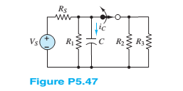
For the circuit in Figure P5.47, assume

Want to see the full answer?
Check out a sample textbook solution
Chapter 5 Solutions
Principles and Applications of Electrical Engineering
- 15arrow_forwardGiven the following, assume 0.7 V votlage drop across LEDs when they are positively biased.(a) When VB=0V, which LED is on?(b) When VB=5V, which LED is on?(c) If you want to limit the current through the LEDs to 10mA for both cases of 3(a) and 3 (b), find out the resistor values of RG and RR.arrow_forwardGiven the following, the intial condtion of output Q is high (H). (a) When /ALM is pushed on, creating a short to ground, what are the inputvoltages of S and R, and the output voltage Q?(b) After (a) happens, /ALM is released. What is the output voltage Q?(c) After (a) and (b) happen, /RESET is pushed on, creating a short to ground,what are the input voltages of S and R, and the output voltage Q?(d) After (a), (b) and (c) happen, /RESET is released. What is the output voltageQ?arrow_forward
 Introductory Circuit Analysis (13th Edition)Electrical EngineeringISBN:9780133923605Author:Robert L. BoylestadPublisher:PEARSON
 Delmar's Standard Textbook Of ElectricityElectrical EngineeringISBN:9781337900348Author:Stephen L. HermanPublisher:Cengage Learning
 Programmable Logic ControllersElectrical EngineeringISBN:9780073373843Author:Frank D. PetruzellaPublisher:McGraw-Hill Education
 Fundamentals of Electric CircuitsElectrical EngineeringISBN:9780078028229Author:Charles K Alexander, Matthew SadikuPublisher:McGraw-Hill Education
 Electric Circuits. (11th Edition)Electrical EngineeringISBN:9780134746968Author:James W. Nilsson, Susan RiedelPublisher:PEARSON
 Engineering ElectromagneticsElectrical EngineeringISBN:9780078028151Author:Hayt, William H. (william Hart), Jr, BUCK, John A.Publisher:Mcgraw-hill Education,


