
Principles and Applications of Electrical Engineering
6th Edition
ISBN: 9780073529592
Author: Giorgio Rizzoni Professor of Mechanical Engineering, James A. Kearns Dr.
Publisher: McGraw-Hill Education
expand_more
expand_more
format_list_bulleted
Videos
Textbook Question
Chapter 5, Problem 5.50HP
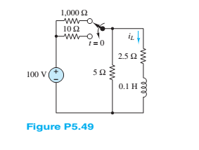
Refer to Figure P5.49 and assume that the switch takes 5 ms to move from one contact to the other. Also assume that during this Lime neither switch position has electrical contact. Find:
a.
b. The maximum voltage between the contacts during the 5-ms duration of the switching.
Hint: This problem requires solving both a turnoff and a turn-on transient problem.
Expert Solution & Answer
Want to see the full answer?
Check out a sample textbook solution
Students have asked these similar questions
Q4. Determine the Y-parameters at a frequency of 100 MHz for the two-port network
shown in figure 4. Present your answer in matrix form.
R1
R-10 m
са
C-20F
11
R2
C1
CF
1-10 H
R
12
C4
C-100 OF
C-50 F
Figure 4
Q3.
a) For the circuit shown in figure 3, use nodal analysis to obtain a
complete set of circuit equations, presenting your answer in
matrix form. Compute the potential across and the current flowing
through the ZL element, given:
IS = 12sin(wt) A, R1 = 30, R2 = 50, L1 = j4 Q, L2 = j10 Q
and ZL = (2+2)
b)
IS
R1
L2
Figure 3
w
R2
ZL
Using equations and text, define the two-port impedance
parameters.
Q3.
The circuit to study is shown in figure below, where
V1 10040° V, V2=50260° V, and
R₁ =3Q, R₂ = 502, R3 = 2, R450, Rs 50, Ls = 12.8 mH. Ls = 6.4 mH,C2 796μF and
C3 =796µF . assume f=50Hz
V1
R1
R3
03
R2
R4
C2
RE
L5
Vx
a)
Apply the mesh current method to obtain a complete set of circuit equations,
presenting your answer in matrix form;
b) Compute the potential across and the current flowing through the L6 elements.
Chapter 5 Solutions
Principles and Applications of Electrical Engineering
Ch. 5 - Write the differential equations fort t0 for iL...Ch. 5 - Write the differential equation fort t0 for vc in...Ch. 5 - Write the differential equation fort t0 for iC in...Ch. 5 - Write the differential equation for t0 for iL in...Ch. 5 - Write the differential equation for t0 for vc in...Ch. 5 - Write the differential equations for t0 for iC and...Ch. 5 - Prob. 5.7HPCh. 5 - Write the differential equation for t0 for iC in...Ch. 5 - Write the differential equation for t0 for iL in...Ch. 5 - Write the differential equations for: t0 for iL...
Ch. 5 - Determine the initial and final conditions on iL...Ch. 5 - Determine the initial and final conditions on vc...Ch. 5 - Determine the initial and final conditions on iC...Ch. 5 - Determine the initial and final conditions on iL...Ch. 5 - Determine the initial and final conditions on vc...Ch. 5 - Determine the initial and final conditions on iC...Ch. 5 - Determine the initial and final conditions on vC...Ch. 5 - Prob. 5.18HPCh. 5 - Prob. 5.19HPCh. 5 - Determine the initial and final conditions on iL...Ch. 5 - At t=0 , just before the switch is opened, the...Ch. 5 - Prob. 5.22HPCh. 5 - Determine the current ic through the capacitor...Ch. 5 - Prob. 5.24HPCh. 5 - Prob. 5.25HPCh. 5 - Assume that steady-state conditions exist in...Ch. 5 - Assume that steady-state conditions exist in the...Ch. 5 - Prob. 5.28HPCh. 5 - Assume that steady-state conditions exist in the...Ch. 5 - Find the Thévenin equivalent network seen by the...Ch. 5 - Prob. 5.31HPCh. 5 - Prob. 5.32HPCh. 5 - Prob. 5.33HPCh. 5 - For t0 , the circuit shown in Figure P5.34 is at...Ch. 5 - The circuit in Figure P5.35 is a simple model of...Ch. 5 - Prob. 5.36HPCh. 5 - Determine the current iC through the capacitor in...Ch. 5 - Determine the voltage vL across the inductor in...Ch. 5 - Prob. 5.39HPCh. 5 - For t0 , the circuit shown in Figure P5.39 is at...Ch. 5 - Prob. 5.41HPCh. 5 - Prob. 5.42HPCh. 5 - Prob. 5.43HPCh. 5 - Prob. 5.44HPCh. 5 - For the circuit shown in Figure P5.41, assume that...Ch. 5 - Prob. 5.46HPCh. 5 - Prob. 5.47HPCh. 5 - For the circuit in Figure P5.47, assume...Ch. 5 - In the circuit in Figure P5.49, how long after the...Ch. 5 - Refer to Figure P5.49 and assume that the switch...Ch. 5 - The circuit in Figure P5.51 includes a...Ch. 5 - At t=0 the switch in the circuit in Figure...Ch. 5 - Prob. 5.53HPCh. 5 - The analogy between electrical and thermal systems...Ch. 5 - The burner and pot of Problem 5.54 can be modeled...Ch. 5 - Prob. 5.56HPCh. 5 - Prob. 5.57HPCh. 5 - Prob. 5.58HPCh. 5 - The circuit in Figure P5.59 models the charging...Ch. 5 - Prob. 5.60HPCh. 5 - In the circuit shown in Figure P5.61:...Ch. 5 - Prob. 5.62HPCh. 5 - If the switch shown in Figure P5.63 is closed at...Ch. 5 - Prob. 5.64HPCh. 5 - Prob. 5.65HPCh. 5 - Prob. 5.66HPCh. 5 - Prob. 5.67HPCh. 5 - Prob. 5.68HPCh. 5 - Assume the switch in the circuit in Figure...Ch. 5 - Prob. 5.70HPCh. 5 - Prob. 5.71HPCh. 5 - Prob. 5.72HPCh. 5 - Prob. 5.73HPCh. 5 - Prob. 5.74HPCh. 5 - Prob. 5.75HPCh. 5 - Prob. 5.76HPCh. 5 - Prob. 5.77HPCh. 5 - Prob. 5.78HPCh. 5 - Prob. 5.79HPCh. 5 - Assume the circuit in Figure P5.80 is in DC steady...Ch. 5 - Prob. 5.81HPCh. 5 - For t0 , determine v in Figure P5.82, assuming DC...
Knowledge Booster


Learn more about
Need a deep-dive on the concept behind this application? Look no further. Learn more about this topic, electrical-engineering and related others by exploring similar questions and additional content below.Similar questions
- a single circuit 50hz transmission line is 362 km long. the load is125mw at 200kv with 100% power factor. 1. evaluate the incident and reflected voltages at the receiving end of the line and at the sending end of the line. 2. determine the line voltage at the sending end from the incident and reflected voltages. 3. computer the wavelength and velocity of propagation. parameters of the line are r = 0.1069 ohms/km. l=1.355mh/km c=8.452nf/km g=0arrow_forwardQ1. Figure 1 shows a differential amplifier. Assume that all transistors are identical. ẞ=180, V = 0.026 Vand V = 0.7V. a) b) Show that the d.c. bias current to the differential pairs is Iccs = 0.6 mA. Calculate the d.c. voltages at the output terminals V。1 and V02- c) Given that the input signals are v₁ = 4 sin(wt) and V₁₂ = 2sin(wt) in mV, find the a.c. voltage between V01 and V02-arrow_forwardQ1. Figure 1 shows a differential amplifier. Assume that all transistors are identical. ẞ=180, V = 0.026 Vand V = 0.7V. a) b) Show that the d.c. bias current to the differential pairs is Iccs = 0.6 mA. Calculate the d.c. voltages at the output terminals V。1 and V02- c) Given that the input signals are v₁ = 4 sin(wt) and V₁₂ = 2sin(wt) in mV, find the a.c. voltage between V01 and V02-arrow_forward
- Q4 Determine the Y-parameters at a frequency of 10 kHz for the two-port network shown in figure below. Present your answer in matrix form. R1 R3 C3 R5 L5 •w• 5 Ohm ww 4 Ohm 200 μF 5 Ohm 8.4 mH 1 Ohm R2 C4 796 µF 400 μF C2arrow_forwardQ1. Figure 1 shows (a) a differential amplifier and (b) a current mirror. All transistors in the circuit are identical and their parameters are: VBE = 0.7 V, VT = 0.026 V, and ẞ = 150. a) Given that the biasing current of Figure 1(a) is I = 1 mA, determine the dc voltages at the output terminals of the differential amplifier. b) Given that the biasing current of Figure 1(a) is I = 1 mA and the ac input signal is via = 1.5 sin(wt) mv, find the corresponding ac output voltage at terminal vo₁ of the differential amplifier. c) In order to provide an output current of 1 mA using on Figure 1(b), find the value for the resistor, R, in Figure 1(b).arrow_forwardQ2. Two op-amp circuits are shown in Figure 2. One of them is an inverting amplifier and the other is a Schmitt trigger. Assume the op-amps used in both circuits are ideal op-amps. The output of the Schmitt trigger is switching between -12 V and +12V (i.e., Vmax = ±12 V). a) Identify which is the inverting amplifier and which is the Schmitt trigger. b) Use the corresponding circuit diagram in Figure 2 to design an inverting amplifier that has a gain of -20 with the output offset voltage minimised. Determine the values of the resistors. c) Select the corresponding circuit diagram in Figure 2 to design a Schmitt trigger that has a lower trigger level of -1 V and an upper trigger level of +2 V. Determine the values of resistors. Sketch the transfer characteristics of this trigger.arrow_forward
- Q2. A simple comparator and a Schmitt trigger are shown in Figures 2(a) and 2(b). The maximum output voltage, Vmax, can switch between -10 V and +10 V for both circuits. The lower and upper trigger levels of the Schmitt trigger are -1 V and +2 V, respectively. a) Based on the information given above, sketch the transfer characteristics for both circuits. b) Show that the hysteresis of the Schmitt trigger of Figure 2(b) can be expressed as 2. R₁- Vmax Vnys R₁ + R₂ c) Using the parameters provided above, determine the ratio of R₂/R₁ for the circuit of Figure 2(b).arrow_forwardDon't use ai to answer I will report you answerarrow_forward3 phase transformer bank is connected with the primaries in deltas and secondaries in wye. Line voltage of the primary is 120V and secondary side is 240V. Required to find the ratio of primary to secondary turns on each of the single phase transformers.arrow_forward
- A generator delivers power through a transmission line to a star-connected load. The system is balanced. Find the values of the currents involved in per unit, considering: (a) single-phase bases and (b) three-phase bases. Datos: S₁ = 2 MVA Vg = 13.2 kV Generador ++ Linea Demanda Pg+jQg Uga ZLT a Zlinea 8.68+j3.162 Zcarga = 70+/10 la ZDa ZD b ZD€ Bases trifásicas: Ug b ZLT b Sb36 = 2 MVA Vb34 = 13.820° kV Ugo ZLTCarrow_forwardcontrol systemarrow_forwardcontrol systemarrow_forward
arrow_back_ios
SEE MORE QUESTIONS
arrow_forward_ios
Recommended textbooks for you
 Introductory Circuit Analysis (13th Edition)Electrical EngineeringISBN:9780133923605Author:Robert L. BoylestadPublisher:PEARSON
 Delmar's Standard Textbook Of ElectricityElectrical EngineeringISBN:9781337900348Author:Stephen L. HermanPublisher:Cengage Learning
 Programmable Logic ControllersElectrical EngineeringISBN:9780073373843Author:Frank D. PetruzellaPublisher:McGraw-Hill Education
 Fundamentals of Electric CircuitsElectrical EngineeringISBN:9780078028229Author:Charles K Alexander, Matthew SadikuPublisher:McGraw-Hill Education
 Electric Circuits. (11th Edition)Electrical EngineeringISBN:9780134746968Author:James W. Nilsson, Susan RiedelPublisher:PEARSON
 Engineering ElectromagneticsElectrical EngineeringISBN:9780078028151Author:Hayt, William H. (william Hart), Jr, BUCK, John A.Publisher:Mcgraw-hill Education,
Introductory Circuit Analysis (13th Edition)
Electrical Engineering
ISBN:9780133923605
Author:Robert L. Boylestad
Publisher:PEARSON
Delmar's Standard Textbook Of Electricity
Electrical Engineering
ISBN:9781337900348
Author:Stephen L. Herman
Publisher:Cengage Learning
Programmable Logic Controllers
Electrical Engineering
ISBN:9780073373843
Author:Frank D. Petruzella
Publisher:McGraw-Hill Education
Fundamentals of Electric Circuits
Electrical Engineering
ISBN:9780078028229
Author:Charles K Alexander, Matthew Sadiku
Publisher:McGraw-Hill Education
Electric Circuits. (11th Edition)
Electrical Engineering
ISBN:9780134746968
Author:James W. Nilsson, Susan Riedel
Publisher:PEARSON
Engineering Electromagnetics
Electrical Engineering
ISBN:9780078028151
Author:Hayt, William H. (william Hart), Jr, BUCK, John A.
Publisher:Mcgraw-hill Education,
Lesson 2 - Source Transformations, Part 2 (Engineering Circuits); Author: Math and Science;https://www.youtube.com/watch?v=7gno74RhVGQ;License: Standard Youtube License