
Videos
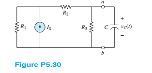
Find the Thévenin equivalent network seen by the capacitor in Figure P5.30 for
Want to see the full answer?
Check out a sample textbook solution
Chapter 5 Solutions
Principles and Applications of Electrical Engineering


- NO AI PLEASE SHOW WORKarrow_forwardNO AI PLEASE SHOW WORKarrow_forwardConsider a Continuous- time LTI System. described by y' (+)+ nycH) = x(+) find yet for усн b) x(+) = u(+) Sul. a) x(+)= ētu(+). c) X(+= √(+) jw few) +2 kW) = X (w) (jw+2) Y(W)= X(w) Han Youn X(w) ½ztjuk a) X (W) = 1 + jw Y(W)= X(w) H(W). I tjw z+jw tjw = 1+jw 2+jw y (+) = (e+ - e²+) 4(+) b) XIW): π (W) + |/|/w Y₁W) = [π √(W) + 1/w] =² + j w zxjw How = π √(w) 1 ㅠ беш) 24jw + *= II 8 (W) + 1 1 1 1 2 4 jw = 2 y(+)= \uct) - e²+us+] - SINAALINE ju 2+ jwarrow_forward
- NO AI PLEASE SHOW WORKarrow_forwardDon't use ai to answer I will report you answerarrow_forwardCompute the Laplace transform of the following time domain function using only L.T. properties: f(t)=(t-3)eu(t-2) The Laplace Transform of x(t) = 8(-1) - u(1) is X(s): = (a) 2πδ(s) (b) 1-1 S (c) j2πδ (s) (d) - 1/3 Sarrow_forward
- Uf you don't know, don't attempt this questions,no Ai or it's screen shot should be usedarrow_forwardFind the initial and final values of sequence x(n) from X(Z) below using the initial and final value properties X(Z) = = z-1arrow_forwardOnly expert should attempt,no Ai or screen shot it solving, I need solution s to all of themarrow_forward
 Introductory Circuit Analysis (13th Edition)Electrical EngineeringISBN:9780133923605Author:Robert L. BoylestadPublisher:PEARSON
 Delmar's Standard Textbook Of ElectricityElectrical EngineeringISBN:9781337900348Author:Stephen L. HermanPublisher:Cengage Learning
 Programmable Logic ControllersElectrical EngineeringISBN:9780073373843Author:Frank D. PetruzellaPublisher:McGraw-Hill Education
 Fundamentals of Electric CircuitsElectrical EngineeringISBN:9780078028229Author:Charles K Alexander, Matthew SadikuPublisher:McGraw-Hill Education
 Electric Circuits. (11th Edition)Electrical EngineeringISBN:9780134746968Author:James W. Nilsson, Susan RiedelPublisher:PEARSON
 Engineering ElectromagneticsElectrical EngineeringISBN:9780078028151Author:Hayt, William H. (william Hart), Jr, BUCK, John A.Publisher:Mcgraw-hill Education,