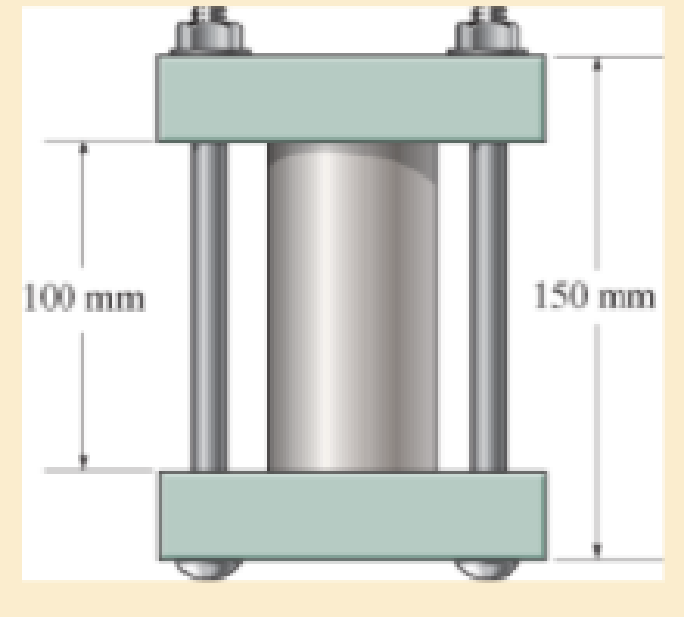
The 50-mm-diameter cylinder is made from Am 1004-T61 magnesium and is placed in the clamp when the temperature is T1=20°C. If the 304-stainless-steel carriage bolts of the clamp each have a diameter of 10 mm, and they hold the cylinder snug with negligible force against the rigid jaws, determine the force in the cylinder when the temperature rises to T2=130°C.

Learn your wayIncludes step-by-step video

Chapter 4 Solutions
Mechanics of Materials (10th Edition)
Additional Engineering Textbook Solutions
Starting Out with C++: Early Objects (9th Edition)
Computer Science: An Overview (13th Edition) (What's New in Computer Science)
Elementary Surveying: An Introduction To Geomatics (15th Edition)
Database Concepts (8th Edition)
Thinking Like an Engineer: An Active Learning Approach (4th Edition)
Starting Out with Java: From Control Structures through Data Structures (4th Edition) (What's New in Computer Science)
- Please draw the front top and side view for the following objectarrow_forwardDraw the top viewarrow_forwardSuppose that a steel of eutectoid composition is cooled to 675°C (1250°F) from 760°C (1400°F) in less than 0.5 s and held at this temperature. (a) How long will it take for the austenite-topearlite reaction to go to 50% completion? To 100% completion? (b) Estimate the hardness of the alloy that has completely transformed to pearlite.arrow_forward
- Problem 2: Determine the components of the reaction at point B (Please use paper sheet + FBD ,don't use chatgpt) MECHANICAL ENGGarrow_forwardARL040_AE_Kn_2of3... Dor Question 4. A two-throw crankshaft has masses distributed as shown: RAH 90 rpm A TRAV B Re Rev M₁ = 15kg; M₂ = 12kg L = 950mm; 1, 350mm; 1₁ = 600mm; 0₁ = 90°; 02=0°; r₁ = 300mm; r250mm The crankshaft is to be balanced by attaching masses at radii of 300 mm and rotating in planes 150 mm outside the planes of number one and number two cranks. Determine the magnitude and angular position of the balance masses. Answer 4.arrow_forwardFEAarrow_forward
- Finite Element Analysisarrow_forwardan experimental research station is constructed on a concrete slab floor. The heat loss from the floor slab is significant, given the cold environment, and is measured to be 5 kW. The edges of the floor slab are insulated with a 60 mm thickness of cellular glass insulation. The width of this insulation at the floor slab is 0.9 m. To avoid excessive fuel consumption, the station air temperature is maintained at a slightly cool temperature of 18ºC. The station is constructed in a square shape, to keep the surface area to volume ratio low; the horizontal dimensions of the floor of the station are 20 m by 20 m. The number of occupants in the research station varies between 5 and 20, depending on the research workload.a) Determine the design outdoor temperature that was used in designing the research station.b) If the floor dimensions of the station are changed to 15 m by 25 m, would the design outdoor temperature that was used in designing the research station from part (a) change? If so,…arrow_forwardFinite element analysisarrow_forward
- a station is constructed on a concrete slab floor. The heat loss from the floor slab is significant, given the cold environment, and is measured to be 5 kW. The edges of the floor slab are insulated with a 60 mm thickness of cellular glass insulation. The width of this insulation at the floor slab is 0.9 m. To avoid excessive fuel consumption, the station air temperature is maintained at a slightly cool temperature of 18ºC. The station is constructed in a square shape, to keep the surface area to volume ratio low; the horizontal dimensions of the floor of the station are 20 m by 20 m. The number of occupants in the research station varies between 5 and 20, depending on the research workload.a) Determine the design outdoor temperature that was used in designing the research station.b) If the floor dimensions of the station are changed to 15 m by 25 m, would the design outdoor temperature that was used in designing the research station from part (a) change? If so, what would it be?…arrow_forwardFinite Element Analysisarrow_forwardFinite Element Analysisarrow_forward
 Elements Of ElectromagneticsMechanical EngineeringISBN:9780190698614Author:Sadiku, Matthew N. O.Publisher:Oxford University Press
 Mechanics of Materials (10th Edition)Mechanical EngineeringISBN:9780134319650Author:Russell C. HibbelerPublisher:PEARSON
 Thermodynamics: An Engineering ApproachMechanical EngineeringISBN:9781259822674Author:Yunus A. Cengel Dr., Michael A. BolesPublisher:McGraw-Hill Education
 Control Systems EngineeringMechanical EngineeringISBN:9781118170519Author:Norman S. NisePublisher:WILEY
 Mechanics of Materials (MindTap Course List)Mechanical EngineeringISBN:9781337093347Author:Barry J. Goodno, James M. GerePublisher:Cengage Learning
 Engineering Mechanics: StaticsMechanical EngineeringISBN:9781118807330Author:James L. Meriam, L. G. Kraige, J. N. BoltonPublisher:WILEY


