
Mechanics of Materials (10th Edition)
10th Edition
ISBN: 9780134319650
Author: Russell C. Hibbeler
Publisher: PEARSON
expand_more
expand_more
format_list_bulleted
Videos
Textbook Question
Chapter 4.5, Problem 4.40P
The A-36 steel pipe has an outer radius of 20 mm and an inner radius of 15 mm. If it fits snugly between the fixed walls before it is loaded, determine the reaction at the walls when it is subjected to the load shown.
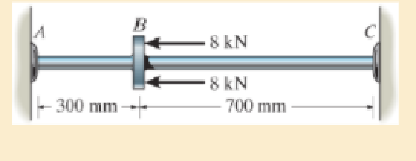
Prob. 4–40
Expert Solution & Answer
Want to see the full answer?
Check out a sample textbook solution
Students have asked these similar questions
One thousand kg/h of a (50-50 wt%) acetone-in-water solution is to be extracted at 25C in a continuous,
countercurrent system with pure 1,1,2-trichloroethane to obtain a raffinate containing 10 wt% acetone. Using the
following equilibrium data, determine with an equilateral-triangle diagram:
a- the minimum flow rate of solvent;
b- the number of stages required for a solvent rate equal to 1.5 times minimum, and composition of each
streamleaving each stage.
c- Repeat the calculation of (a) and (b) if the solvent used has purity 93wt% (4wr% acetone, 3wt% water
impurities)
acetone water
1,1,2-trichloroethane
Raffinate. Weight
Extract. Weight
0.6
0.13
0.27
Fraction Acetone
Fraction Acetone
0.5
0.04
0.46
0.44
0.56
0.4
0.03
0.57
0.29
0.40
0.3
0.02
0.68
0.12
0.18
0.2
0.015
0.785
0.0
0.0
0.1
0.01
0.89
0.55
0.35
0.1
0.5
0.43
0.07
0.4
0.57
0.03
0.3
0.68
0.02
0.2
0.79
0.01
0.1
0.895
0.005
2500 kg/hr of (20-80) nicotine water solution is to be extracted with benzene containing 0.5% nicotine in
the 1st and 2ed stages while the 3rd stage is free of nicotine. Cross- current operation is used with different amounts
of solvent for each stages 2000kg/hr in the 1st stage, 2300 kg/hr in the 2nd stage, 2600 kg/hr in the 3rd,
determine: -
a- The final raffinate concentration and % extraction.
b-
b- The minimum amount of solvent required for counter-current operation if the minimum concentration
will be reduced to 5% in the outlet raffinate.
Equilibrium data
Wt % Nicotine in water
Wt % Nicotine in benzene
0
4
16
25
0
4
21
30
Quiz/An eccentrically loaded bracket is welded to the support as shown in Figure below. The load is static. The weld size
for weld w1 is h1=6mm, for w2 h2 5mm, and for w3 is h3 -5.5 mm. Determine the safety factor (S.f) for the welds.
F=22 kN. Use an AWS Electrode type (E90xx).
140
101.15
REDMI NOTE 8 PRO
AI QUAD CAMERA
F
Chapter 4 Solutions
Mechanics of Materials (10th Edition)
Ch. 4.2 - In each case, determine the internal normal force...Ch. 4.2 - Determine the internal normal force between...Ch. 4.2 - The post weighs 8kN/m. Determine the internal...Ch. 4.2 - The rod is subjected to an external axial force of...Ch. 4.2 - The rigid beam supports the load of 60 kN....Ch. 4.2 - The 20-mm-diameter A-36 steel rod is subjected to...Ch. 4.2 - Segments AB and CD of the assembly are solid...Ch. 4.2 - The 30-mm-diameter A992 steel rod is subjected to...Ch. 4.2 - If the 20-mm-diameter rod is made of A-36 steel...Ch. 4.2 - The 20-mm-diameter 2014-T6 aluminum rod is...
Ch. 4.2 - The 20-mm-diameter 2014-T6 aluminum rod is...Ch. 4.2 - The A992 steel rod is subjected to the loading...Ch. 4.2 - The copper shaft is subjected to the axial loads...Ch. 4.2 - The composite shaft, consisting of aluminum,...Ch. 4.2 - The composite shaft, consisting of aluminum,...Ch. 4.2 - The 2014-T6 aluminium rod has a diameter of 30 mm...Ch. 4.2 - The A-36 steel drill shaft of an oil well extends...Ch. 4.2 - The truss is made of three A-36 steel members,...Ch. 4.2 - The truss is made of three A-36 steel members,...Ch. 4.2 - The assembly consists of two 10-mm diameter red...Ch. 4.2 - The assembly consists of two 10-mm diameter red...Ch. 4.2 - The load is supported by the four 304 stainless...Ch. 4.2 - The load is supported by the four 304 stainless...Ch. 4.2 - The rigid bar is supported by the pin-connected...Ch. 4.2 - The post is made of Douglas fir and has a diameter...Ch. 4.2 - The post is made of Douglas fir and has a diameter...Ch. 4.2 - The coupling rod is subjected to a force of 5 kip....Ch. 4.2 - The pipe is stuck in the ground so that when it is...Ch. 4.2 - The is made of three pin-connected A992 steel...Ch. 4.2 - The linkage is made of three pin connected A992...Ch. 4.2 - The assembly consists of three titanium...Ch. 4.2 - The rigid beam is supported at its ends by two...Ch. 4.2 - The rigid beam is supported at its ends by two...Ch. 4.2 - The steel bar has the original dimensions shown in...Ch. 4.2 - Determine the relative displacement of one end of...Ch. 4.2 - The assembly consists of two rigid bars that are...Ch. 4.2 - The truss consists of three members, each made...Ch. 4.2 - Solve Prob. 426 when the load P acts vertically...Ch. 4.2 - The observation cage C has a weight of 250 kip and...Ch. 4.2 - The steel bar has the original dimensions shown in...Ch. 4.2 - The ball is truncated at its ends and is used to...Ch. 4.5 - The column is constructed from high-strength...Ch. 4.5 - The column is constructed from high-strength...Ch. 4.5 - The A-36 steel pipe has a 6061-T6 aluminum core....Ch. 4.5 - If column AB is made from high strength precast...Ch. 4.5 - If column AB is made from high strength precast...Ch. 4.5 - Determine the support reactions at the rigid...Ch. 4.5 - If the supports at A and C are flexible and have a...Ch. 4.5 - The load of 2000 lb is to be supported by the two...Ch. 4.5 - The load of 2000 lb is to be supported by the two...Ch. 4.5 - The A-36 steel pipe has an outer radius of 20 mm...Ch. 4.5 - The 10-mm-diameter steel bolt is surrounded by a...Ch. 4.5 - The 10-mm-diameter steel bolt is surrounded by a...Ch. 4.5 - The assembly consists of two red brass C83400...Ch. 4.5 - The rigid beam is supported by the three suspender...Ch. 4.5 - The bolt AB has a diameter of 20 mm and passes...Ch. 4.5 - If the gap between C and the rigid wall at D is...Ch. 4.5 - The support consists of a solid red brass C83400...Ch. 4.5 - If there are n fibers, each having a...Ch. 4.5 - The rigid bar is pinned at A and supported by two...Ch. 4.5 - The rigid bar is pinned at A and supported by two...Ch. 4.5 - The rigid bar is pinned at A and supported by two...Ch. 4.5 - The rigid bar is pinned at A and supported by two...Ch. 4.5 - The 2014-T6 aluminum rod AC is reinforced with the...Ch. 4.5 - The 2014-T6 aluminum rod AC is reinforced with the...Ch. 4.5 - The three suspender bars are made of A992 steel...Ch. 4.5 - The three A-36 steel wires each have a diameter of...Ch. 4.5 - The A-36 steel wires AB and AD each have a...Ch. 4.5 - The post is made from 6061-T6 aluminum and has a...Ch. 4.5 - The post is made from 6061-T6 aluminum and has a...Ch. 4.5 - The bracket is held to the wall using three A-36...Ch. 4.5 - The bracket is held to the wall using three A-36...Ch. 4.5 - If each of the posts has an unloaded length of 1 m...Ch. 4.5 - The rigid bar is supported by the two short white...Ch. 4.5 - The assembly consists of two posts AB and CD each...Ch. 4.5 - The assembly consists of two posts AB and CD each...Ch. 4.5 - The assembly consists of two posts AB and CD each...Ch. 4.5 - The wheel is subjected to a force of 18 kN from...Ch. 4.6 - The C83400-red-brass rod AB and 2014-T6- aluminum...Ch. 4.6 - The assembly has the diameters and material...Ch. 4.6 - The rod is made of A992 steel and has a diameter...Ch. 4.6 - The two cylindrical rod segments are fixed to the...Ch. 4.6 - The two cylindrical rod segments are fixed to the...Ch. 4.6 - The pipe is made of A992 steel and is connected to...Ch. 4.6 - The bronze C86100 pipe has an inner radius of 0.5...Ch. 4.6 - The 40-ft-long A-36 steel rails on a train track...Ch. 4.6 - The device is used to measure a change in...Ch. 4.6 - The bar has a cross-sectional area A, length L,...Ch. 4.6 - When the temperature is at 30C, the A-36 steel...Ch. 4.6 - When the temperature is at 30C, the A-36 steel...Ch. 4.6 - When the temperature is at 30C, the A-36 steel...Ch. 4.6 - The 50-mm-diameter cylinder is made from Am...Ch. 4.6 - The 50-mm-diameter cylinder is made from Am...Ch. 4.6 - The wires AB and AC are made of steel, and wire AD...Ch. 4.6 - The cylinder CD of the assembly is heated from T1...Ch. 4.6 - The cylinder CD of the assembly is heated from T1=...Ch. 4.6 - The metal strap has a thickness t and width w and...Ch. 4.9 - Determine the maximum normal stress developed in...Ch. 4.9 - If the allowable normal stress for the bar is...Ch. 4.9 - The steel bar has the dimensions shown. Determine...Ch. 4.9 - The A-36 steel plate has a thickness of 12 mm. If...Ch. 4.9 - Determine the maximum axial force P that can be...Ch. 4.9 - Determine the maximum normal stress developed in...Ch. 4.9 - The member is to be made from a steel plate that...Ch. 4.9 - The resulting stress distribution along section AB...Ch. 4.9 - The resulting stress distribution along section AB...Ch. 4.9 - Prob. 4.96PCh. 4.9 - The weight is suspended from steel and aluminum...Ch. 4.9 - The bar has a cross-sectional area of 0.5 in2 and...Ch. 4.9 - The distributed loading is applied to the rigid...Ch. 4.9 - The distributed loading is applied to the rigid...Ch. 4.9 - The rigid lever arm is supported by two A-36 steel...Ch. 4.9 - The rigid lever arm is supported by two A-36 steel...Ch. 4.9 - The 300-kip weight is slowly set on the top of a...Ch. 4.9 - The rigid beam is supported by three 25-mm...Ch. 4.9 - The rigid beam is supported by three 25-mm...Ch. 4.9 - The rigid beam is supported by the three posts A,...Ch. 4.9 - The rigid beam is supported by the three posts A,...Ch. 4.9 - The bar having a diameter of 2 in. is fixed...Ch. 4.9 - Determine the elongation of the bar in Prob.4108...Ch. 4.9 - The rigid beam is supported by three A-36 steel...Ch. 4 - The assembly consists of two A992 steel bolts AB...Ch. 4 - The assembly shown consists of two A992 steel...Ch. 4 - The rods each have the same 25-mm diameter and...Ch. 4 - Two A992 steel pipes, each having a...Ch. 4 - The force P is applied to the bar, which is made...Ch. 4 - The 2014-T6 aluminum rod has a diameter of 0.5 in....Ch. 4 - The 2014-T6 aluminum rod has a diameter of 0.5 in....Ch. 4 - The rigid link is supported by a pin at A and two...Ch. 4 - The joint is made from three A992 steel plates...
Knowledge Booster


Learn more about
Need a deep-dive on the concept behind this application? Look no further. Learn more about this topic, mechanical-engineering and related others by exploring similar questions and additional content below.Similar questions
- (read image)arrow_forwardProblem 3.30 A piston-cylinder device contains 0.85 kg of refrigerant- 134a at -10°C. The piston that is free to move has a mass of 12 kg and a diameter of 25 cm. The local atmospheric pressure is 100 kPa. Now, heat is transferred to refrigerant-134a until the temperature is 15°C. Determine (a) the final pressure, (b) the change in the volume of the refrigerant, and (c) the change in the enthalpy of the refrigerant-134a. please show Al work step by steparrow_forwardPart 1 The storage tank contains lubricating oil of specific gravity 0.86 In one inclined side of the tank, there is a 0.48 m diameter circular inspection door, mounted on a horizontal shaft along the centre line of the gate. The oil level in the tank rests 8.8 m above the mounted shaft. (Please refer table 01 for relevant SG, D and h values). Describe the hydrostatic force and centre of pressure with the aid of a free body diagram of the inspection door. Calculate the magnitude of the hydrostatic force and locate the centre of pressure. 45° Estimate the moment that would have to be applied to the shaft to open the gate. Stop B If the oil level raised by 2 m from the current level, calculate the new moment required to open the gate. Figure 01arrow_forward
- From thermodynamics please fill in the table show all work step by steparrow_forwardThe 150-lb skater passes point A with a speed of 6 ft/s. (Figure 1) Determine his speed when he reaches point B. Neglect friction. Determine the normal force exerted on him by the track at this point. 25 ft B = 4x A 20 ft xarrow_forwardA virtual experiment is designed to determine the effect of friction on the timing and speed of packages being delivered to a conveyor belt and the normal force applied to the tube. A package is held and then let go at the edge of a circular shaped tube of radius R = 5m. The particle at the bottom will transfer to the conveyor belt, as shown below. Run the simulations for μ = 0, 0.1, 0.2, 0.3, 0.4, 0.5, 0.6 and determine the time and speed at which the package is delivered to the conveyor belt. In addition, determine the maximum normal force and its location along the path as measured by angle 0. Submit in hardcopy form: (0) Free Body Diagram, equations underneath, derivations (a) Your MATLAB mfile (b) A table listing the values in 5 columns: μ, T (time of transfer), V (speed of transfer), 0 (angle of max N), Nmax (max N) (c) Based on your results, explain in one sentence what you think will happen to the package if the friction is increased even further, e.g. μ = 0.8. NOTE: The ODE is…arrow_forward
- Patm = 1 bar Piston m = 50 kg 5 g of Air T₁ = 600 K P₁ = 3 bar Stops A 9.75 x 10⁻³ m² FIGURE P3.88arrow_forwardAssume a Space Launch System (Figure 1(a)) that is approximated as a cantilever undamped single degree of freedom (SDOF) system with a mass at its free end (Figure 1(b)). The cantilever is assumed to be massless. Assume a wind load that is approximated with a concentrated harmonic forcing function p(t) = posin(ωt) acting on the mass. The known properties of the SDOF and the applied forcing function are given below. • Mass of SDOF: m =120 kip/g • Acceleration of gravity: g = 386 in/sec2 • Bending sectional stiffness of SDOF: EI = 1015 lbf×in2 • Height of SDOF: h = 2000 inches • Amplitude of forcing function: po = 6 kip • Forcing frequency: f = 8 Harrow_forwardAssume a Space Launch System (Figure 1(a)) that is approximated as a cantilever undamped single degree of freedom (SDOF) system with a mass at its free end (Figure 1(b)). The cantilever is assumed to be massless. Assume a wind load that is approximated with a concentrated harmonic forcing function p(t) = posin(ωt) acting on the mass. The known properties of the SDOF and the applied forcing function are given below. • Mass of SDOF: m =120 kip/g • Acceleration of gravity: g = 386 in/sec2 • Bending sectional stiffness of SDOF: EI = 1015 lbf×in2 • Height of SDOF: h = 2000 inches • Amplitude of forcing function: po = 6 kip • Forcing frequency: f = 8 Hz Figure 1: Single-degree-of-freedom system in Problem 1. Please compute the following considering the steady-state response of the SDOF system. Do not consider the transient response unless it is explicitly stated in the question. (a) The natural circular frequency and the natural period of the SDOF. (10 points) (b) The maximum displacement of…arrow_forward
- Assume a Space Launch System (Figure 1(a)) that is approximated as a cantilever undamped single degree of freedom (SDOF) system with a mass at its free end (Figure 1(b)). The cantilever is assumed to be massless. Assume a wind load that is approximated with a concentrated harmonic forcing function p(t) = posin(ωt) acting on the mass. The known properties of the SDOF and the applied forcing function are given below. • Mass of SDOF: m =120 kip/g • Acceleration of gravity: g = 386 in/sec2 • Bending sectional stiffness of SDOF: EI = 1015 lbf×in2 • Height of SDOF: h = 2000 inches • Amplitude of forcing function: po = 6 kip • Forcing frequency: f = 8 Hz Figure 1: Single-degree-of-freedom system in Problem 1. Please compute the following considering the steady-state response of the SDOF system. Do not consider the transient response unless it is explicitly stated in the question. (a) The natural circular frequency and the natural period of the SDOF. (10 points) (b) The maximum displacement of…arrow_forwardPlease solve 13 * √(2675.16)² + (63.72 + 2255,03)² = 175x106 can you explain the process for getting d seperate thank youarrow_forwardIf the 300-kg drum has a center of mass at point G, determine the horizontal and vertical components of force acting at pin A and the reactions on the smooth pads C and D. The grip at B on member DAB resists both horizontal and vertical components of force at the rim of the drum. P 60 mm; 60 mm: 600 mm A E 30° B C 390 mm 100 mm D Garrow_forward
arrow_back_ios
SEE MORE QUESTIONS
arrow_forward_ios
Recommended textbooks for you
 Elements Of ElectromagneticsMechanical EngineeringISBN:9780190698614Author:Sadiku, Matthew N. O.Publisher:Oxford University Press
 Mechanics of Materials (10th Edition)Mechanical EngineeringISBN:9780134319650Author:Russell C. HibbelerPublisher:PEARSON
 Thermodynamics: An Engineering ApproachMechanical EngineeringISBN:9781259822674Author:Yunus A. Cengel Dr., Michael A. BolesPublisher:McGraw-Hill Education
 Control Systems EngineeringMechanical EngineeringISBN:9781118170519Author:Norman S. NisePublisher:WILEY
 Mechanics of Materials (MindTap Course List)Mechanical EngineeringISBN:9781337093347Author:Barry J. Goodno, James M. GerePublisher:Cengage Learning
 Engineering Mechanics: StaticsMechanical EngineeringISBN:9781118807330Author:James L. Meriam, L. G. Kraige, J. N. BoltonPublisher:WILEY
Elements Of Electromagnetics
Mechanical Engineering
ISBN:9780190698614
Author:Sadiku, Matthew N. O.
Publisher:Oxford University Press
Mechanics of Materials (10th Edition)
Mechanical Engineering
ISBN:9780134319650
Author:Russell C. Hibbeler
Publisher:PEARSON
Thermodynamics: An Engineering Approach
Mechanical Engineering
ISBN:9781259822674
Author:Yunus A. Cengel Dr., Michael A. Boles
Publisher:McGraw-Hill Education
Control Systems Engineering
Mechanical Engineering
ISBN:9781118170519
Author:Norman S. Nise
Publisher:WILEY
Mechanics of Materials (MindTap Course List)
Mechanical Engineering
ISBN:9781337093347
Author:Barry J. Goodno, James M. Gere
Publisher:Cengage Learning
Engineering Mechanics: Statics
Mechanical Engineering
ISBN:9781118807330
Author:James L. Meriam, L. G. Kraige, J. N. Bolton
Publisher:WILEY
Differences between Temporary Joining and Permanent Joining.; Author: Academic Gain Tutorials;https://www.youtube.com/watch?v=PTr8QZhgXyg;License: Standard Youtube License