
Mechanics of Materials (10th Edition)
10th Edition
ISBN: 9780134319650
Author: Russell C. Hibbeler
Publisher: PEARSON
expand_more
expand_more
format_list_bulleted
Concept explainers
Videos
Textbook Question
Chapter 4.2, Problem 4.2PP
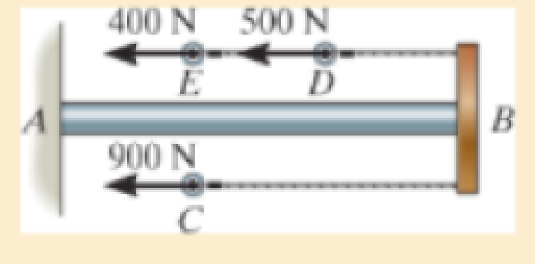
Determine the internal normal force between lettered points on the cable and rod. Draw all necessary free-body diagrams.
Expert Solution & Answer

Learn your wayIncludes step-by-step video

schedule03:13
Students have asked these similar questions
13.38 Consider the attic of a home located in a hot climate.
The floor of the attic is characterized by a width of
L₁ = 8 m while the roof makes an angle of 0 = 30° from
the horizontal direction, as shown in the schematic.
The homeowner wishes to reduce the heat load to the
home by adhering bright aluminum foil (ε = 0.07) onto
the surfaces of the attic space. Prior to installation of
the foil, the surfaces are of emissivity & = 0.90.
Attic
A2, 82, T2 0 = 30°
A1, E1, T₁
土
L₁ = 8 m
(a) Consider installation on the bottom of the attic
roof only. Determine the ratio of the radiation heat
transfer after to before the installation of the foil.
(b) Determine the ratio of the radiation heat transfer
after to before installation if the foil is installed
only on the top of the attic floor.
(c) Determine the ratio of the radiation heat transfer if
the foil is installed on both the roof bottom and the
floor top.
13.1
Determine F2 and F2 for the following configura-
tions using the reciprocity theorem and other basic
shape factor relations. Do not use tables or charts.
(a) Small sphere of area A, under a concentric hemi-
sphere of area A₂ = 3A₁
A₂
A1
(a)
(b) Long duct. Also, what is F₁₂?
A₂
Αν
(b)
(c) Long inclined plates (point B is directly above the
center of A₁)
B
100 mm
A₂
- 220 mm
(c)
(d) Long cylinder lying on infinite plane
+
A₁
Az
(d)
(e) Hemisphere-disk arrangement
-A₂, hemisphere,
diameter D
A₂
A₁, disk,
diameter D/2
(e)
(f) Long, open channel
1 m
AA₂
2 m
(f)
(g) Long cylinders with A₁ = 4A₁. Also, what is F₁₂?
-D₁
A1
-A₂
-D2
(e)
(h) Long, square rod in a long cylinder. Also, what
is F22?
w=D/5
18
A₁
-A2
(h)
-D
13.9 Determine the shape factor, F12, for the rectangles
shown.
6 m
1
3 m
6 m
1 m
2
6 m
1
0.5 m
2
1 m
(a) Perpendicular rectangles
without a common edge.
-1 m.
(b) Parallel rectangles of
unequal areas.
Chapter 4 Solutions
Mechanics of Materials (10th Edition)
Ch. 4.2 - In each case, determine the internal normal force...Ch. 4.2 - Determine the internal normal force between...Ch. 4.2 - The post weighs 8kN/m. Determine the internal...Ch. 4.2 - The rod is subjected to an external axial force of...Ch. 4.2 - The rigid beam supports the load of 60 kN....Ch. 4.2 - The 20-mm-diameter A-36 steel rod is subjected to...Ch. 4.2 - Segments AB and CD of the assembly are solid...Ch. 4.2 - The 30-mm-diameter A992 steel rod is subjected to...Ch. 4.2 - If the 20-mm-diameter rod is made of A-36 steel...Ch. 4.2 - The 20-mm-diameter 2014-T6 aluminum rod is...
Ch. 4.2 - The 20-mm-diameter 2014-T6 aluminum rod is...Ch. 4.2 - The A992 steel rod is subjected to the loading...Ch. 4.2 - The copper shaft is subjected to the axial loads...Ch. 4.2 - The composite shaft, consisting of aluminum,...Ch. 4.2 - The composite shaft, consisting of aluminum,...Ch. 4.2 - The 2014-T6 aluminium rod has a diameter of 30 mm...Ch. 4.2 - The A-36 steel drill shaft of an oil well extends...Ch. 4.2 - The truss is made of three A-36 steel members,...Ch. 4.2 - The truss is made of three A-36 steel members,...Ch. 4.2 - The assembly consists of two 10-mm diameter red...Ch. 4.2 - The assembly consists of two 10-mm diameter red...Ch. 4.2 - The load is supported by the four 304 stainless...Ch. 4.2 - The load is supported by the four 304 stainless...Ch. 4.2 - The rigid bar is supported by the pin-connected...Ch. 4.2 - The post is made of Douglas fir and has a diameter...Ch. 4.2 - The post is made of Douglas fir and has a diameter...Ch. 4.2 - The coupling rod is subjected to a force of 5 kip....Ch. 4.2 - The pipe is stuck in the ground so that when it is...Ch. 4.2 - The is made of three pin-connected A992 steel...Ch. 4.2 - The linkage is made of three pin connected A992...Ch. 4.2 - The assembly consists of three titanium...Ch. 4.2 - The rigid beam is supported at its ends by two...Ch. 4.2 - The rigid beam is supported at its ends by two...Ch. 4.2 - The steel bar has the original dimensions shown in...Ch. 4.2 - Determine the relative displacement of one end of...Ch. 4.2 - The assembly consists of two rigid bars that are...Ch. 4.2 - The truss consists of three members, each made...Ch. 4.2 - Solve Prob. 426 when the load P acts vertically...Ch. 4.2 - The observation cage C has a weight of 250 kip and...Ch. 4.2 - The steel bar has the original dimensions shown in...Ch. 4.2 - The ball is truncated at its ends and is used to...Ch. 4.5 - The column is constructed from high-strength...Ch. 4.5 - The column is constructed from high-strength...Ch. 4.5 - The A-36 steel pipe has a 6061-T6 aluminum core....Ch. 4.5 - If column AB is made from high strength precast...Ch. 4.5 - If column AB is made from high strength precast...Ch. 4.5 - Determine the support reactions at the rigid...Ch. 4.5 - If the supports at A and C are flexible and have a...Ch. 4.5 - The load of 2000 lb is to be supported by the two...Ch. 4.5 - The load of 2000 lb is to be supported by the two...Ch. 4.5 - The A-36 steel pipe has an outer radius of 20 mm...Ch. 4.5 - The 10-mm-diameter steel bolt is surrounded by a...Ch. 4.5 - The 10-mm-diameter steel bolt is surrounded by a...Ch. 4.5 - The assembly consists of two red brass C83400...Ch. 4.5 - The rigid beam is supported by the three suspender...Ch. 4.5 - The bolt AB has a diameter of 20 mm and passes...Ch. 4.5 - If the gap between C and the rigid wall at D is...Ch. 4.5 - The support consists of a solid red brass C83400...Ch. 4.5 - If there are n fibers, each having a...Ch. 4.5 - The rigid bar is pinned at A and supported by two...Ch. 4.5 - The rigid bar is pinned at A and supported by two...Ch. 4.5 - The rigid bar is pinned at A and supported by two...Ch. 4.5 - The rigid bar is pinned at A and supported by two...Ch. 4.5 - The 2014-T6 aluminum rod AC is reinforced with the...Ch. 4.5 - The 2014-T6 aluminum rod AC is reinforced with the...Ch. 4.5 - The three suspender bars are made of A992 steel...Ch. 4.5 - The three A-36 steel wires each have a diameter of...Ch. 4.5 - The A-36 steel wires AB and AD each have a...Ch. 4.5 - The post is made from 6061-T6 aluminum and has a...Ch. 4.5 - The post is made from 6061-T6 aluminum and has a...Ch. 4.5 - The bracket is held to the wall using three A-36...Ch. 4.5 - The bracket is held to the wall using three A-36...Ch. 4.5 - If each of the posts has an unloaded length of 1 m...Ch. 4.5 - The rigid bar is supported by the two short white...Ch. 4.5 - The assembly consists of two posts AB and CD each...Ch. 4.5 - The assembly consists of two posts AB and CD each...Ch. 4.5 - The assembly consists of two posts AB and CD each...Ch. 4.5 - The wheel is subjected to a force of 18 kN from...Ch. 4.6 - The C83400-red-brass rod AB and 2014-T6- aluminum...Ch. 4.6 - The assembly has the diameters and material...Ch. 4.6 - The rod is made of A992 steel and has a diameter...Ch. 4.6 - The two cylindrical rod segments are fixed to the...Ch. 4.6 - The two cylindrical rod segments are fixed to the...Ch. 4.6 - The pipe is made of A992 steel and is connected to...Ch. 4.6 - The bronze C86100 pipe has an inner radius of 0.5...Ch. 4.6 - The 40-ft-long A-36 steel rails on a train track...Ch. 4.6 - The device is used to measure a change in...Ch. 4.6 - The bar has a cross-sectional area A, length L,...Ch. 4.6 - When the temperature is at 30C, the A-36 steel...Ch. 4.6 - When the temperature is at 30C, the A-36 steel...Ch. 4.6 - When the temperature is at 30C, the A-36 steel...Ch. 4.6 - The 50-mm-diameter cylinder is made from Am...Ch. 4.6 - The 50-mm-diameter cylinder is made from Am...Ch. 4.6 - The wires AB and AC are made of steel, and wire AD...Ch. 4.6 - The cylinder CD of the assembly is heated from T1...Ch. 4.6 - The cylinder CD of the assembly is heated from T1=...Ch. 4.6 - The metal strap has a thickness t and width w and...Ch. 4.9 - Determine the maximum normal stress developed in...Ch. 4.9 - If the allowable normal stress for the bar is...Ch. 4.9 - The steel bar has the dimensions shown. Determine...Ch. 4.9 - The A-36 steel plate has a thickness of 12 mm. If...Ch. 4.9 - Determine the maximum axial force P that can be...Ch. 4.9 - Determine the maximum normal stress developed in...Ch. 4.9 - The member is to be made from a steel plate that...Ch. 4.9 - The resulting stress distribution along section AB...Ch. 4.9 - The resulting stress distribution along section AB...Ch. 4.9 - Prob. 4.96PCh. 4.9 - The weight is suspended from steel and aluminum...Ch. 4.9 - The bar has a cross-sectional area of 0.5 in2 and...Ch. 4.9 - The distributed loading is applied to the rigid...Ch. 4.9 - The distributed loading is applied to the rigid...Ch. 4.9 - The rigid lever arm is supported by two A-36 steel...Ch. 4.9 - The rigid lever arm is supported by two A-36 steel...Ch. 4.9 - The 300-kip weight is slowly set on the top of a...Ch. 4.9 - The rigid beam is supported by three 25-mm...Ch. 4.9 - The rigid beam is supported by three 25-mm...Ch. 4.9 - The rigid beam is supported by the three posts A,...Ch. 4.9 - The rigid beam is supported by the three posts A,...Ch. 4.9 - The bar having a diameter of 2 in. is fixed...Ch. 4.9 - Determine the elongation of the bar in Prob.4108...Ch. 4.9 - The rigid beam is supported by three A-36 steel...Ch. 4 - The assembly consists of two A992 steel bolts AB...Ch. 4 - The assembly shown consists of two A992 steel...Ch. 4 - The rods each have the same 25-mm diameter and...Ch. 4 - Two A992 steel pipes, each having a...Ch. 4 - The force P is applied to the bar, which is made...Ch. 4 - The 2014-T6 aluminum rod has a diameter of 0.5 in....Ch. 4 - The 2014-T6 aluminum rod has a diameter of 0.5 in....Ch. 4 - The rigid link is supported by a pin at A and two...Ch. 4 - The joint is made from three A992 steel plates...
Additional Engineering Textbook Solutions
Find more solutions based on key concepts
Using FilesPopulation Bar Chart Write a program that produces a bar chart showing the population growth of Prai...
Starting Out with C++: Early Objects (9th Edition)
For the circuit shown, use the node-voltage method to find v1, v2, and i1.
How much power is delivered to the c...
Electric Circuits. (11th Edition)
What is a mutator function? What is an accessor function?
Starting Out with C++ from Control Structures to Objects (9th Edition)
What are the six steps of a soldering operation?
Degarmo's Materials And Processes In Manufacturing
Big data Big data describes datasets with huge volumes that are beyond the ability of typical database manageme...
Management Information Systems: Managing The Digital Firm (16th Edition)
In programming we use the term string to mean _____. a. many lines of code b. parallel memory locations c. stri...
Starting Out With Visual Basic (8th Edition)
Knowledge Booster


Learn more about
Need a deep-dive on the concept behind this application? Look no further. Learn more about this topic, mechanical-engineering and related others by exploring similar questions and additional content below.Similar questions
- I keep getting the wrong answer i have gotten 6519.87 and 319.71arrow_forwardthank you for previous answer I apologize if the acceleration was unclear it is underlined now along with values in tablesarrow_forward११११११११ TABLE Much 160,000kg Croll 0,005 CD Ap Par ng При nchs 0.15 5m² 1.2kg/m³ 0.98 0.9 0,98 0,9 0,88 IF 20 10 to add The train is going to make several stops along its journey. It will be important for the train to accelerate quickdy to get back up to speed. In order to get Tesla Model S motors until we get the combined The Forque and power needed we are goins bined power and forque needed to accelerate from 0 to 324 km/hr in less than 5 Minutes. Tesla Prated 270 kW Tesla Trated Twheel ng Jaxle 440 NM 20 8.5kgm² 0.45M a) What is the minimum whole number of Tesla Motors required to achieve accelerate the train from 0 to 324 km/hr in less than 5 Nnutes? Seperate the acceleration into constant torque and constant power 0. b) How long does it take the train to accelerate from 0 to 324 km/hr with the number of Tesla motors from part a? c) Using Matlab plot the relocity profile as a function of time, Is this a constant acceleration profile? Barrow_forward
- Example find f(t)? -4s F(s)= (s² + 4)²arrow_forwarddraw a kinematic diagramarrow_forwardRigid bodies ENG2016. Full complete solutions need okk don't use guidelines but solve full accurate steps by steps don't use chat gpt or any other ai okkk just solve complete solutions okkk take your time but solve complete solutionsarrow_forward
- Question 6 I need to show all work step by step dynamicsarrow_forwardQu. 3 The automobile is originally at rest s = 0. If it then starts to increase its speed at i = (0.05t2)ft/s?, where t is in seconds, determine the magnitudes of its velocity and acceleration at s = 550 ft. please show all work from dynamics step by step formulaarrow_forwardquestion 5 and 6 from dynamics I need to show all work step by step problemsarrow_forward
- Study Area Document Sharing User Settings Access Pearson mylabmastering.pearson.com P Pearson MyLab and Mastering The crash cushion for a highway barrier consists of a nest of barrels filled with an impact-absorbing material. The barrier stopping force is measured versus the vehicle penetration into the barrier. (Figure 1) Part A P Course Home b My Questions | bartleby Review Determine the distance a car having a weight of 4000 lb will penetrate the barrier if it is originally traveling at 55 ft/s when it strikes the first barrel. Express your answer to three significant figures and include the appropriate units. Figure 1 of 1 36 μΑ S = Value Units Submit Request Answer Provide Feedback ? Next >arrow_forwardWater is the working fluid in an ideal Rankine cycle. Saturated vapor enters the turbine at 12 MPa, and the condenser pressure is 8 kPa. The mass flow rate of steam entering the turbine is 50 kg/s. Determine: (a) the net power developed, in kW. (b) the rate of heat transfer to the steam passing through the boiler, in kW. (c) the percent thermal efficiency. (d) the mass flow rate of condenser cooling water, in kg/s, if the cooling water undergoes a temperature increase of 18°C with negligible pressure change in passing through the condenser.arrow_forward4. The figure below shows a bent pipe with the external loading FA 228 lb, and M₁ = M₂ = 1 kip-ft. The force Fernal loading FA = 300 lb, FB: parallel to the y-axis, and and yc = 60°. = 125 lb, Fc = acts parallel to the x-z plane, the force FB acts Cartesian resultan Coordinate direction angles of Fc are ac = 120°, ẞc = 45°, a. Compute the resultant force vector of the given external loading and express it in EST form. b. Compute the resultant moment vector of the given external loading about the origin, O, and express it in Cartesian vector form. Use the vector method while computing the moments of forces. c. Compute the resultant moment vector of the given external loading about the line OA and express it in Cartesian vector form. :00 PM EST k ghoufran@buffaternal du 2 ft M₁ A 40° FA M2 C 18 in 1 ft Fc 25 houfran@bald.edu - Feb 19, 3 ft FBarrow_forward
arrow_back_ios
SEE MORE QUESTIONS
arrow_forward_ios
Recommended textbooks for you
 International Edition---engineering Mechanics: St...Mechanical EngineeringISBN:9781305501607Author:Andrew Pytel And Jaan KiusalaasPublisher:CENGAGE L
International Edition---engineering Mechanics: St...
Mechanical Engineering
ISBN:9781305501607
Author:Andrew Pytel And Jaan Kiusalaas
Publisher:CENGAGE L
Engineering Basics - Statics & Forces in Equilibrium; Author: Solid Solutions - Professional Design Solutions;https://www.youtube.com/watch?v=dQBvQ2hJZFg;License: Standard YouTube License, CC-BY