
Concept explainers
Videos
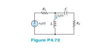
Use phasor techniques to solve for
Want to see the full answer?
Check out a sample textbook solution
Chapter 4 Solutions
Principles and Applications of Electrical Engineering


- I need help with this problem and an explanation of the solution for the image described below. (Introduction to Signals and Systems)arrow_forwardFind Rth at the open terminals using 1V test source.arrow_forwardHow many atoms are there in a simple cubic unit cell? in a bcc unit cell? in a fcc unit cell? in the unit cell characterizing the diamond lattice?arrow_forward
- Consider the homogeneous RLC circuit (no voltage source) shown in the diagram below. Before the switch is closed, the capacitor has an initial charge go and the circuit has an initial current go- R 9(1) i(t)↓ After the switches closes, current flows through the circuit and the capacitor begins to discharge. The equation that describes the total voltage in the loop comes from Kirchoff's voltage law: L di(t) + Ri(t)+(0) = 0, (1) where i(t) and q(t) are the current and capacitor charge as a function of time, L is the inductance, R is the resistance, and C is the capacitance. Using the fact that the current equals the rate of change of the capacitor charge, and dividing by L, we can write the following homogeneous (no input source) differential equation for the charge on the capacitor: 4(1) +29(1)+w79(1)=0, ཀྱི where a= R 2L and The solution to this second order linear differential equation can be written as: 9(1) =Aent - Beat, where (3) (4) (5) A= (81+20)90 +90 (82+20)90 +90 and B= (6)…arrow_forwardConsider the homogeneous RLC circuit (no voltage source) shown in the diagram below. Before the switch is closed, the capacitor has an initial charge go and the circuit has an initial current go. R w i(t) q(t) C н After the switches closes, current flows through the circuit and the capacitor begins to discharge. The equation that describes the total voltage in the loop comes from Kirchoff's voltage law: di(t) L + Ri(t) + (t) = 0, dt (1) where i(t) and q(t) are the current and capacitor charge as a function of time, L is the inductance, R is the resistance, and C is the capacitance. Using the fact that the current equals the rate of change of the capacitor charge, and dividing by L, we can write the following homogeneous (no input source) differential equation for the charge on the capacitor: ä(t)+2ag(t)+wg(t) = 0, (2) where R a 2L and w₁ = C LC The solution to this second order linear differential equation can be written as: where 81= q(t) = Ae³¹- Bel 82 = (3) (4) (5)arrow_forwardI need help with this problem and an explanation of the solution for the image described below. (Introduction to Signals and Systems)arrow_forward
 Introductory Circuit Analysis (13th Edition)Electrical EngineeringISBN:9780133923605Author:Robert L. BoylestadPublisher:PEARSON
 Delmar's Standard Textbook Of ElectricityElectrical EngineeringISBN:9781337900348Author:Stephen L. HermanPublisher:Cengage Learning
 Programmable Logic ControllersElectrical EngineeringISBN:9780073373843Author:Frank D. PetruzellaPublisher:McGraw-Hill Education
 Fundamentals of Electric CircuitsElectrical EngineeringISBN:9780078028229Author:Charles K Alexander, Matthew SadikuPublisher:McGraw-Hill Education
 Electric Circuits. (11th Edition)Electrical EngineeringISBN:9780134746968Author:James W. Nilsson, Susan RiedelPublisher:PEARSON
 Engineering ElectromagneticsElectrical EngineeringISBN:9780078028151Author:Hayt, William H. (william Hart), Jr, BUCK, John A.Publisher:Mcgraw-hill Education,