
Concept explainers
Videos
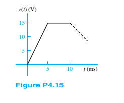
The voltage across a generic element X has the waveform shown in Figure P4.15. For
a.
b.
c. 7-mH inductor.
(a)
The current through the given element for the given voltage waveform.
To plot:
A graph of current through the element for
Answer to Problem 4.15HP
The current through the given element for the given voltage waveform is
A graph of current through the element for
Explanation of Solution
Given information:
Element is resistor and its value is
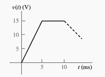
The given voltage waveform is shown below.

Calculation:
Consider the given graph for the voltage.
For
For
So, voltage can be written as
The given element is resistor. The current across it will be
Voltage
For
For
Current
A graph of current with respect to time is shown below.
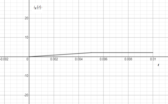
Figure 1
(b)
The current through the given element for the given voltage waveform.
To plot:
A graph of current through the element for
Answer to Problem 4.15HP
The current through the given element for the given voltage waveform is
A graph of current through the element for
Explanation of Solution
Given information:
Element is capacitor and its value is
The given voltage waveform is shown below.

Calculation:
Consider the given graph for the voltage.
For
For
So, voltage can be written as
The given element is capacitor. The current across it will be
Voltage
For
For
Current
A graph of current with respect to time is shown below.
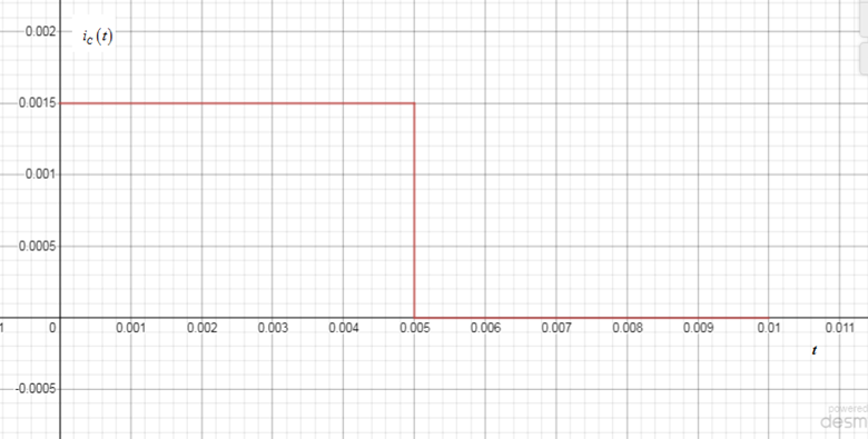
Figure 2
(c)
The current through the given element for the given voltage waveform.
To plot:
A graph of current through the element for
Answer to Problem 4.15HP
The current through the given element for the given voltage waveform is
A graph of current through the element for
Explanation of Solution
Given information:
Element is inductor and its value is
The given voltage waveform is shown below.
Calculation:
Consider the given graph for the voltage.
For
For
So, voltage can be written as
The given element is inductor. The current across it will be
Voltage
For
For
Current
A graph of current with respect to time is shown below.
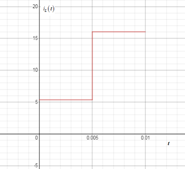
Figure 3
Want to see more full solutions like this?
Chapter 4 Solutions
Principles and Applications of Electrical Engineering


- 7. MOSFET circuit The MOSFET in the circuit below has V₁ = 1 V and kn = 4 mA/V². a) Is the MOSFET operating in saturation or in the triode region? b) Determine the drain current ID and Vout. + 5 V 5 k Voutarrow_forwardNot use ai pleasearrow_forward5. MOSFET circuit The MOSFET in the circuit below has Vt = 0.5 V and kn = 0.4 mA/V2. Determine Vout. + 5 V 1 mA - Vout 6. MOSFET circuit The MOSFET in the circuit below has V₁ = 1 V and kn = 2 mA/V². a) Is the MOSFET operating in saturation or in the triode region? b) Determine the drain current ID. +2V 2 V -2 Varrow_forward
- A.With the aid of a diagram, describe fringing, and explain the impact that it has on the relevant magnetic circuit parameter. B. A coil of 1500 turns give rise to a magnetic flux of 2.5 mWb when carrying a certain current. If this current is reversed in 0.2 s, what is the average value of the e.m.f. induced in the coil? C.Define Mutual Inductance.Two coils are connected in series and their total inductance is measured as 0.12 H, and when the connection to one coil is reversed, the total inductance is measured as 0.04 H. If the coefficient of coupling is 0.8, determine:The self-inductance of each coil, and the mutual inductance between the coils.arrow_forwardcomparing Lenz's law and the left hand generator rule, which of these is the more important fundamental principle?arrow_forwardExample: Electric Field and Potential Inside a Charged Sphere Problem: A sphere of radius R = 0.2 m is uniformly charged with a total charge Q = 5 μC. The sphere is made of a dielectric material with relative permittivity € = 4. Calculate: 1. The electric field intensity E(r) inside and outside the sphere. 2. The electric potential (r) at any point inside the sphere. Solution: Step 1: Given Data Radius of the sphere: R = 0.2m, Total charge: Q-5 μC=5× 10° C. Step 2: Electric Field Inside the Sphere (< Using Gauss's Law:arrow_forwardarrow_back_iosSEE MORE QUESTIONSarrow_forward_ios
 Introductory Circuit Analysis (13th Edition)Electrical EngineeringISBN:9780133923605Author:Robert L. BoylestadPublisher:PEARSON
 Delmar's Standard Textbook Of ElectricityElectrical EngineeringISBN:9781337900348Author:Stephen L. HermanPublisher:Cengage Learning
 Programmable Logic ControllersElectrical EngineeringISBN:9780073373843Author:Frank D. PetruzellaPublisher:McGraw-Hill Education
 Fundamentals of Electric CircuitsElectrical EngineeringISBN:9780078028229Author:Charles K Alexander, Matthew SadikuPublisher:McGraw-Hill Education
 Electric Circuits. (11th Edition)Electrical EngineeringISBN:9780134746968Author:James W. Nilsson, Susan RiedelPublisher:PEARSON
 Engineering ElectromagneticsElectrical EngineeringISBN:9780078028151Author:Hayt, William H. (william Hart), Jr, BUCK, John A.Publisher:Mcgraw-hill Education,