
Principles and Applications of Electrical Engineering
6th Edition
ISBN: 9780073529592
Author: Giorgio Rizzoni Professor of Mechanical Engineering, James A. Kearns Dr.
Publisher: McGraw-Hill Education
expand_more
expand_more
format_list_bulleted
Concept explainers
Videos
Textbook Question
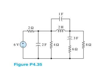
Chapter 4, Problem 4.35HP
Assume steady-state conditions and find the energy stored in each capacitor and inductor shown in FigureP4.35.
Expert Solution & Answer
Want to see the full answer?
Check out a sample textbook solution
Students have asked these similar questions
A professor teaches two sections of a course:
• 70% of students are in Section 1, and 30% are in Section 2.
•
In Section 1, 90% of students pass the final exam.
•
In Section 2, 80% of students pass the final exam.
A student is randomly selected.
a) Draw a tree diagram to represent this situation.
b) What is the probability that the selected student passes the exam?
c) Given that a student failed, what is the probability they were from Section 1?
.. A factory has two machines, A and B. Machine A produces 60% of the parts, while Machine B
produces 40%. Machine A produces defective parts 5% of the time, while Machine B produces defective
parts 10% of the time. A randomly selected part from production is inspected.
a) Draw a tree diagram to represent the probability of getting a defective part.
b) What is the probability that a randomly selected part is defective?
c) If a part is found to be defective, what is the probability it came from Machine A?
A Factory produces light bulbs from two different machines: Machine A and Machine B. The
probability that a randomly selected light bulbs is from Machine A is 60%, and the probability that a light
bulb is defective is 5%. Suppose that probability that a light bulb is defective given that it was made by
Machine A is 0.05. Similarly, the probability that a light bulb is defective given that it was made by
Machine B is 0.03. Are the events “the light bulb is from Machine A” and “the light bulb is defective”
independent?
Chapter 4 Solutions
Principles and Applications of Electrical Engineering
Ch. 4 - The current through a 0.8-H inductor is given by...Ch. 4 - For each case shown below, derive the expression...Ch. 4 - Derive the expression for the voltage across...Ch. 4 - In the circuit shown in Figure P4.4, assume R=1...Ch. 4 - Prob. 4.5HPCh. 4 - In the circuit shown in Figure P4.4, assume R=2...Ch. 4 - In the circuit shown in Figure P4.7, assume R=2...Ch. 4 - Prob. 4.8HPCh. 4 - Prob. 4.9HPCh. 4 - Prob. 4.10HP
Ch. 4 - The voltage waveform shown in Figure P4.10 is...Ch. 4 - The voltage across a 0.5-mH inductor, Plotted as a...Ch. 4 - Prob. 4.13HPCh. 4 - The current through a 16-H inductor is zero at t=0...Ch. 4 - The voltage across a generic element X has the...Ch. 4 - The plots shown in Figure P4.16 are the voltage...Ch. 4 - The plots shown in Figure P4.17 are the voltage...Ch. 4 - The plots shown in Figure P4.18 are the voltage...Ch. 4 - The plots shown in Figure P4.19 are the voltage...Ch. 4 - The voltage vL(t) across a 10-mH inductor is shown...Ch. 4 - The current through a 2-H inductor is p1otted in...Ch. 4 - Prob. 4.22HPCh. 4 - Prob. 4.23HPCh. 4 - Prob. 4.24HPCh. 4 - The voltage vC(t) across a capacitor is shown in...Ch. 4 - The voltage vL(t) across an inductor is shown in...Ch. 4 - Find the average and rms values of x(t) when:...Ch. 4 - The output voltage waveform of a controlled...Ch. 4 - Refer to Problem 4.28 and find the angle + that...Ch. 4 - Find the ratio between the average and rms value...Ch. 4 - The current through a 1- resistor is shown in...Ch. 4 - Derive the ratio between the average and rms value...Ch. 4 - Find the rms value of the current waveform shown...Ch. 4 - Determine the rms (or effective) value of...Ch. 4 - Assume steady-state conditions and find the energy...Ch. 4 - Assume steady-state conditions and find the energy...Ch. 4 - Find the phasor form of the following functions:...Ch. 4 - Convert the following complex numbers to...Ch. 4 - Convert the rectangular factors to polar form and...Ch. 4 - Complete the following exercises in complex...Ch. 4 - Convert the following expressions to rectangular...Ch. 4 - Find v(t)=v1(t)+v2(t) where...Ch. 4 - The current through and the voltage across a...Ch. 4 - Express the sinusoidal waveform shown in Figure...Ch. 4 - Prob. 4.45HPCh. 4 - Convert the following pairs of voltage and current...Ch. 4 - Determine the equivalent impedance seen by the...Ch. 4 - Determine the equivalent impedance seen by the...Ch. 4 - The generalized version of Ohm’s law for impedance...Ch. 4 - Prob. 4.50HPCh. 4 - Determine the voltage v2(t) across R2 in the...Ch. 4 - Determine the frequency so that the current Ii...Ch. 4 - Prob. 4.53HPCh. 4 - Use phasor techniques to solve for the current...Ch. 4 - Use phasor techniques to solve for the voltage...Ch. 4 - Prob. 4.56HPCh. 4 - Solve for VR shown in Figure P4.57. Assume:...Ch. 4 - With reference to Problem 4.55, find the value of ...Ch. 4 - Find the current iR(t) through the resistor shown...Ch. 4 - Find vout(t) shown in Figure P4.60.Ch. 4 - Find the impedance Z shown in Figure...Ch. 4 - Find the sinusoidal steady-state output vout(t)...Ch. 4 - Determine the voltage vL(t) across the inductor...Ch. 4 - Determine the current iR(t) through the resistor...Ch. 4 - Find the frequency that causes the equivalent...Ch. 4 - a. Find the equivalent impedance Zo seen by the...Ch. 4 - A common model for a practical capacitor has...Ch. 4 - Using phasor techniques, solve for vR2 shown in...Ch. 4 - Using phasor techniques to solve for iL in the...Ch. 4 - Determine the Thévenin equivalent network seen by...Ch. 4 - Determine the Norton equivalent network seen by...Ch. 4 - Use phasor techniques to solve for iL(t) in...Ch. 4 - Use mesh analysis to determine the currents i1(t)...Ch. 4 - Prob. 4.74HPCh. 4 - Prob. 4.75HPCh. 4 - Find the Thévenin equivalent network seen by the...Ch. 4 - Prob. 4.77HPCh. 4 - Prob. 4.78HPCh. 4 - Prob. 4.79HPCh. 4 - Prob. 4.80HPCh. 4 - Use mesh analysis to find the phasor mesh current...Ch. 4 - Write the node equations required to solve for all...Ch. 4 - Determine Vo in the circuit of Figure...Ch. 4 - Prob. 4.84HP
Knowledge Booster


Learn more about
Need a deep-dive on the concept behind this application? Look no further. Learn more about this topic, electrical-engineering and related others by exploring similar questions and additional content below.Similar questions
- 3 (10pts). A Factory produces light bulbs from two different machines: Machine A and Machine B. The probability that a randomly selected light bulbs is from Machine A is 60%, and the probability that a light bulb is defective is 5%. Suppose that probability that a light bulb is defective given that it was made by Machine A is 0.05. Similarly, the probability that a light bulb is defective given that it was made by Machine B is 0.03. Are the events "the light bulb is from Machine A" and "the light bulb is defective" independent?arrow_forwardPlease see the followinggn imagearrow_forwardImage is attachedarrow_forward
- Using Carson's rule, determine the transmission bandwidth for commercial FM radio broadcasting, provided that the maximum value of frequency deviation is 75 kHz and the bandwidth of the audio signal is 15 kHzarrow_forward2. Laboratory Preliminary Discussion First-order High-pass RC Filter Analysis The first-order high-pass RC filter shown in figure 3 below represents all voltages and currents in the time domain. We will again convert the circuit to its s-domain equivalent as shown in figure 4 and apply Laplace transform techniques. ic(t) C vs(t) i₁(t) + + vc(t) R1 ww Vi(t) || 12(t) V2(t) R₂ Vout(t) VR2(t) = V2(t) Figure 3: A first-order high-pass RC filter represented in the time domain. Ic(s) C + Vs(s) I₁(s) + + Vc(s) R₁ www V₁(s) 12(s) V₂(s) R₂ Vout(S) = VR2(S) = V2(s) Figure 4: A first-order high-pass RC filter represented in the s-domain. Again, to generate the s-domain expression for the output voltage, You (S) = V2 (s), for the circuit shown in figure 4 above, we can apply voltage division in the s-domain as shown in equation 2 below. Equation 2 will be used in the prelab computations to find an expression for the output voltage, xc(t), in the time domain. equation (2) R₂ Vout(s) = V₂(s) = R₂+…arrow_forwardCan you show me the steps to get the last part after the second equal sign.arrow_forward
arrow_back_ios
SEE MORE QUESTIONS
arrow_forward_ios
Recommended textbooks for you
 Introductory Circuit Analysis (13th Edition)Electrical EngineeringISBN:9780133923605Author:Robert L. BoylestadPublisher:PEARSON
 Delmar's Standard Textbook Of ElectricityElectrical EngineeringISBN:9781337900348Author:Stephen L. HermanPublisher:Cengage Learning
 Programmable Logic ControllersElectrical EngineeringISBN:9780073373843Author:Frank D. PetruzellaPublisher:McGraw-Hill Education
 Fundamentals of Electric CircuitsElectrical EngineeringISBN:9780078028229Author:Charles K Alexander, Matthew SadikuPublisher:McGraw-Hill Education
 Electric Circuits. (11th Edition)Electrical EngineeringISBN:9780134746968Author:James W. Nilsson, Susan RiedelPublisher:PEARSON
 Engineering ElectromagneticsElectrical EngineeringISBN:9780078028151Author:Hayt, William H. (william Hart), Jr, BUCK, John A.Publisher:Mcgraw-hill Education,
Introductory Circuit Analysis (13th Edition)
Electrical Engineering
ISBN:9780133923605
Author:Robert L. Boylestad
Publisher:PEARSON
Delmar's Standard Textbook Of Electricity
Electrical Engineering
ISBN:9781337900348
Author:Stephen L. Herman
Publisher:Cengage Learning
Programmable Logic Controllers
Electrical Engineering
ISBN:9780073373843
Author:Frank D. Petruzella
Publisher:McGraw-Hill Education
Fundamentals of Electric Circuits
Electrical Engineering
ISBN:9780078028229
Author:Charles K Alexander, Matthew Sadiku
Publisher:McGraw-Hill Education
Electric Circuits. (11th Edition)
Electrical Engineering
ISBN:9780134746968
Author:James W. Nilsson, Susan Riedel
Publisher:PEARSON
Engineering Electromagnetics
Electrical Engineering
ISBN:9780078028151
Author:Hayt, William H. (william Hart), Jr, BUCK, John A.
Publisher:Mcgraw-hill Education,
Capacitors Explained - The basics how capacitors work working principle; Author: The Engineering Mindset;https://www.youtube.com/watch?v=X4EUwTwZ110;License: Standard YouTube License, CC-BY