
The current
Answer to Problem 4.10HP
The expression for the current through the inductor for different time interval is
Explanation of Solution
Calculation:
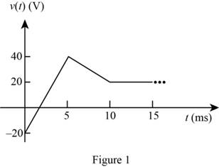
The given diagram is shown in Figure 1
The conversion from
The conversion from
The conversion from
The conversion from
The conversion from
The conversion from
The conversion from
The conversion from
From the graph the expression for the voltage between the points
From the graph the expression for the voltage between the points
From the graph the expression for the voltage at
The expression for the voltage across the inductor is given by,
The expression for the current through the inductor is given by,
Substitute
Substitute
Substitute
Substitute
Substitute
Substitute
Substitute
Substitute
The expression for the current through the inductor is given by,
Conclusion:
Therefore, the expression for the current through the inductor for different time interval is
Want to see more full solutions like this?
Chapter 4 Solutions
Principles and Applications of Electrical Engineering

- 2) (15pts) In a PAM baseband digital communication system, an M-ary system has a channel bandwidth of 2 KHz. The channel introduces 10dB of losses and AWGN noise with a power spectral density of 1*10-6 W/Hz. The application requires a bit rate of 4.8 Kbps and BER of less than 10^-6. Estimate the require transmit power.arrow_forwardi need helppp pleasearrow_forward1) (2pts) If you know you have a bad clock (lots of jitter) and you are not bandwidth constrained, you should: (Circle the correct answer) a) Set the roll off factor to zero b) Set the roll off factor to ½ c) Set the roll off factor to one 2) (2pts) Short answer: Why do we use M-ary modulation? 3) (4 pts) Short answer: The application engineer comes to your desk and says that the error rate is too high and must be reduced for the application to function correctly. The system is battery operated. What do you tell them is the trade- off?arrow_forward
- i need helppp pleasearrow_forward5) (20 pts) You are testing a system that has pulse shape shown below for Logic 1 and Logic 0. You are connecting the transmitter to an oscilloscope which is set up to display the resulting eye-diagram of the system. Sketch what you would expect to see on the oscilloscope for an ideal system (an ideal system is noiseless and jitter free) Logic 1 3 volts Time 0 Ть Logic 0 0 Ть Time -2 voltsarrow_forward4. (20 pts) You are given a channel with the following impulse response. Determine the set of equations that will be used to determine the coefficients of a Zero-Forcing Linear Equalizer. DO NOT SOLVE FOR THE COEFFICIENTS. Just show the set of equation that would be used to solved the coefficients. 0 m≤-31 -0.33 m = -2 .25 m = -1 h(mb) = 1 m = 0 -0.45 m = 1 0.5 m = 2 0 m≥3arrow_forward
- I need help understanding part B. See attached photo.arrow_forwardi need helppp pleasearrow_forward3) (30pts) An application requires a bit rate of 18.2 Kbps and an error rate of less than 104. The channel has a noise power spectral density of 10-8 W/Hz. The channel attenuates the power in the signal by 5 dB. The system uses binary PAM baseband digital communication system with the minimum required bandwidth and a roll-off factor of 0.319. a) (10 pts) What is the estimated minimum required signal power (Pt) at the transmitter?arrow_forward
 Introductory Circuit Analysis (13th Edition)Electrical EngineeringISBN:9780133923605Author:Robert L. BoylestadPublisher:PEARSON
 Delmar's Standard Textbook Of ElectricityElectrical EngineeringISBN:9781337900348Author:Stephen L. HermanPublisher:Cengage Learning
 Programmable Logic ControllersElectrical EngineeringISBN:9780073373843Author:Frank D. PetruzellaPublisher:McGraw-Hill Education
 Fundamentals of Electric CircuitsElectrical EngineeringISBN:9780078028229Author:Charles K Alexander, Matthew SadikuPublisher:McGraw-Hill Education
 Electric Circuits. (11th Edition)Electrical EngineeringISBN:9780134746968Author:James W. Nilsson, Susan RiedelPublisher:PEARSON
 Engineering ElectromagneticsElectrical EngineeringISBN:9780078028151Author:Hayt, William H. (william Hart), Jr, BUCK, John A.Publisher:Mcgraw-hill Education,