
Principles and Applications of Electrical Engineering
6th Edition
ISBN: 9780073529592
Author: Giorgio Rizzoni Professor of Mechanical Engineering, James A. Kearns Dr.
Publisher: McGraw-Hill Education
expand_more
expand_more
format_list_bulleted
Videos
Textbook Question
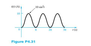
Chapter 4, Problem 4.31HP
The current through a
Expert Solution & Answer
Want to see the full answer?
Check out a sample textbook solution
Students have asked these similar questions
Practice1
A single-phase step-down transformer of 83 kVA, nominal voltages 24kV/230 V, frequency 60 Hz is available.The following test parameters are available:Pfe = 216 W, Io = 2% Pcc = 1083 W, Vcc = 4%
Determine:a. Parameters Rcc, Xcc and Rfe of the equivalent circuit referring to the secondary.b. Relative voltage drops. εcc, εrcc, εxcc
A single-phase step-down transformer of 83 kVA, nominal voltages 24kV/230 V, frequency 60 Hz is available.The following test parameters are available:Pfe = 216W, Io = 2%, Pcc = 1083W, Vcc = 4%
Determine:
If the transformer is connected to 24 kV, a load Zc, fp = 0.866 in arrears, is installed in the secondary transformer, which consumes the nominal current. Calculate:• Transformer voltage regulation (perform calculations by PU's)• Maximum efficiency.
The magnetic circuit shown in the figure is made of TRAN-COR material, the flow magnetic power on the right arm (BCDE) is 6 x 10 -4 Wb. (disregard marginal effects anddispersion)
Calculate the current in the 200-turn coil
Chapter 4 Solutions
Principles and Applications of Electrical Engineering
Ch. 4 - The current through a 0.8-H inductor is given by...Ch. 4 - For each case shown below, derive the expression...Ch. 4 - Derive the expression for the voltage across...Ch. 4 - In the circuit shown in Figure P4.4, assume R=1...Ch. 4 - Prob. 4.5HPCh. 4 - In the circuit shown in Figure P4.4, assume R=2...Ch. 4 - In the circuit shown in Figure P4.7, assume R=2...Ch. 4 - Prob. 4.8HPCh. 4 - Prob. 4.9HPCh. 4 - Prob. 4.10HP
Ch. 4 - The voltage waveform shown in Figure P4.10 is...Ch. 4 - The voltage across a 0.5-mH inductor, Plotted as a...Ch. 4 - Prob. 4.13HPCh. 4 - The current through a 16-H inductor is zero at t=0...Ch. 4 - The voltage across a generic element X has the...Ch. 4 - The plots shown in Figure P4.16 are the voltage...Ch. 4 - The plots shown in Figure P4.17 are the voltage...Ch. 4 - The plots shown in Figure P4.18 are the voltage...Ch. 4 - The plots shown in Figure P4.19 are the voltage...Ch. 4 - The voltage vL(t) across a 10-mH inductor is shown...Ch. 4 - The current through a 2-H inductor is p1otted in...Ch. 4 - Prob. 4.22HPCh. 4 - Prob. 4.23HPCh. 4 - Prob. 4.24HPCh. 4 - The voltage vC(t) across a capacitor is shown in...Ch. 4 - The voltage vL(t) across an inductor is shown in...Ch. 4 - Find the average and rms values of x(t) when:...Ch. 4 - The output voltage waveform of a controlled...Ch. 4 - Refer to Problem 4.28 and find the angle + that...Ch. 4 - Find the ratio between the average and rms value...Ch. 4 - The current through a 1- resistor is shown in...Ch. 4 - Derive the ratio between the average and rms value...Ch. 4 - Find the rms value of the current waveform shown...Ch. 4 - Determine the rms (or effective) value of...Ch. 4 - Assume steady-state conditions and find the energy...Ch. 4 - Assume steady-state conditions and find the energy...Ch. 4 - Find the phasor form of the following functions:...Ch. 4 - Convert the following complex numbers to...Ch. 4 - Convert the rectangular factors to polar form and...Ch. 4 - Complete the following exercises in complex...Ch. 4 - Convert the following expressions to rectangular...Ch. 4 - Find v(t)=v1(t)+v2(t) where...Ch. 4 - The current through and the voltage across a...Ch. 4 - Express the sinusoidal waveform shown in Figure...Ch. 4 - Prob. 4.45HPCh. 4 - Convert the following pairs of voltage and current...Ch. 4 - Determine the equivalent impedance seen by the...Ch. 4 - Determine the equivalent impedance seen by the...Ch. 4 - The generalized version of Ohm’s law for impedance...Ch. 4 - Prob. 4.50HPCh. 4 - Determine the voltage v2(t) across R2 in the...Ch. 4 - Determine the frequency so that the current Ii...Ch. 4 - Prob. 4.53HPCh. 4 - Use phasor techniques to solve for the current...Ch. 4 - Use phasor techniques to solve for the voltage...Ch. 4 - Prob. 4.56HPCh. 4 - Solve for VR shown in Figure P4.57. Assume:...Ch. 4 - With reference to Problem 4.55, find the value of ...Ch. 4 - Find the current iR(t) through the resistor shown...Ch. 4 - Find vout(t) shown in Figure P4.60.Ch. 4 - Find the impedance Z shown in Figure...Ch. 4 - Find the sinusoidal steady-state output vout(t)...Ch. 4 - Determine the voltage vL(t) across the inductor...Ch. 4 - Determine the current iR(t) through the resistor...Ch. 4 - Find the frequency that causes the equivalent...Ch. 4 - a. Find the equivalent impedance Zo seen by the...Ch. 4 - A common model for a practical capacitor has...Ch. 4 - Using phasor techniques, solve for vR2 shown in...Ch. 4 - Using phasor techniques to solve for iL in the...Ch. 4 - Determine the Thévenin equivalent network seen by...Ch. 4 - Determine the Norton equivalent network seen by...Ch. 4 - Use phasor techniques to solve for iL(t) in...Ch. 4 - Use mesh analysis to determine the currents i1(t)...Ch. 4 - Prob. 4.74HPCh. 4 - Prob. 4.75HPCh. 4 - Find the Thévenin equivalent network seen by the...Ch. 4 - Prob. 4.77HPCh. 4 - Prob. 4.78HPCh. 4 - Prob. 4.79HPCh. 4 - Prob. 4.80HPCh. 4 - Use mesh analysis to find the phasor mesh current...Ch. 4 - Write the node equations required to solve for all...Ch. 4 - Determine Vo in the circuit of Figure...Ch. 4 - Prob. 4.84HP
Knowledge Booster


Learn more about
Need a deep-dive on the concept behind this application? Look no further. Learn more about this topic, electrical-engineering and related others by exploring similar questions and additional content below.Similar questions
- theoretically and compare it with the test value. Report :- 1- Calculate the D.C. output Voltagearrow_forwardf 2- For resistive load, measured the output voltage by using oscilloscope, then sketch this wave.. 3- Measure the average values of Vɩ and Iɩ . 4- Repeat steps 2 & 3 but for R.L load.arrow_forwardA single-phase 10 kVA, 1000/100V transformer has the relative voltage parameters of: εrcc = 6%, εxcc = 8%, core losses Pfe = 200W and nominal copper losses of Pcu = 300W.A load of 2 < 30° Ω is connected to the secondary of the transformer. Determine using pu ́s calculations:to. The voltage in the primary, if the voltage of the secondary (at load) is 100 V.b. If the voltage in the primary remains constant at 1000 V, what would be the voltage at the load?c. The voltage regulation of the transformer under the conditions b.d. The efficiency of the transformer under the conditions b.arrow_forward
- 9.38 For the op-amp circuit of Fig. P9.38:(a) Obtain an expression for H(w) = Vo/Vs in standard form.(b) Generate spectral plots for the magnitude and phase ofH(w), given that R1 = 99 kW, R2 = 1 kW, and C = 0.1 μF.(c) What type of filter is it? What is its maximum gain?arrow_forwardA short 3-o transmission line with an impedance of (6+j 8)2 per phase has receiving end of 22000 kw, 120 KV, 0.8 lagging p.f. Determine (i) Sending voltage (ii) Sending current (iii) Sending power factor (iv) voltage regulation.arrow_forward9.37 For the op-amp circuit of Fig. P9.37:*(a) Obtain an expression for H(w) = Vo/Vs in standard form.(b) Generate spectral plots for the magnitude and phase ofH(w), given that R1 = 1 kW, R2 = 4 kW, and C = 1 μF.(c) What type of filter is it? What is its maximum gainarrow_forward
- I need a detailed drawing with explanation Solve es 4 = -20125 شكا +981X914 pv + 96852 الإنجليزية (second order differential I need an example on the subject the partition method and the Laplace method. Suggest an easy equations) and you solve it using and simple example for me and solve it using two methods, only one example. 750 01 95Parrow_forwardNot use ai pleasearrow_forwardし الإنجليزية (second order differential I need an example on the subject the partition method and the equations) and you solve it using Laplace method. Suggest an easy and simple example for me and solve it using two methods, only one example. الله X 9.01 P+96erarrow_forward
- I need an example on the subject (second order differential equations) and you solve it using the partition method and the Laplace method. Suggest an easy and simple example for me and solve it using two methods, only one example.arrow_forward5- Discuss your resultsarrow_forwardWrite a program to flash three LED's connected to ports (8, 9 & 10) respectively as shown below: (Note: T₁-T3-5s & T₂=3s) LED, (pin 10) 2. Suen LED₂ (pin 9) LED, (pin 8) T₁'T' T'arrow_forward
arrow_back_ios
SEE MORE QUESTIONS
arrow_forward_ios
Recommended textbooks for you
 Introductory Circuit Analysis (13th Edition)Electrical EngineeringISBN:9780133923605Author:Robert L. BoylestadPublisher:PEARSON
 Delmar's Standard Textbook Of ElectricityElectrical EngineeringISBN:9781337900348Author:Stephen L. HermanPublisher:Cengage Learning
 Programmable Logic ControllersElectrical EngineeringISBN:9780073373843Author:Frank D. PetruzellaPublisher:McGraw-Hill Education
 Fundamentals of Electric CircuitsElectrical EngineeringISBN:9780078028229Author:Charles K Alexander, Matthew SadikuPublisher:McGraw-Hill Education
 Electric Circuits. (11th Edition)Electrical EngineeringISBN:9780134746968Author:James W. Nilsson, Susan RiedelPublisher:PEARSON
 Engineering ElectromagneticsElectrical EngineeringISBN:9780078028151Author:Hayt, William H. (william Hart), Jr, BUCK, John A.Publisher:Mcgraw-hill Education,
Introductory Circuit Analysis (13th Edition)
Electrical Engineering
ISBN:9780133923605
Author:Robert L. Boylestad
Publisher:PEARSON
Delmar's Standard Textbook Of Electricity
Electrical Engineering
ISBN:9781337900348
Author:Stephen L. Herman
Publisher:Cengage Learning
Programmable Logic Controllers
Electrical Engineering
ISBN:9780073373843
Author:Frank D. Petruzella
Publisher:McGraw-Hill Education
Fundamentals of Electric Circuits
Electrical Engineering
ISBN:9780078028229
Author:Charles K Alexander, Matthew Sadiku
Publisher:McGraw-Hill Education
Electric Circuits. (11th Edition)
Electrical Engineering
ISBN:9780134746968
Author:James W. Nilsson, Susan Riedel
Publisher:PEARSON
Engineering Electromagnetics
Electrical Engineering
ISBN:9780078028151
Author:Hayt, William H. (william Hart), Jr, BUCK, John A.
Publisher:Mcgraw-hill Education,
ECE320 Lecture1-3c: Steady-State Error, System Type; Author: Rose-Hulman Online;https://www.youtube.com/watch?v=hG7dq-51AAg;License: Standard Youtube License