
Principles and Applications of Electrical Engineering
6th Edition
ISBN: 9780073529592
Author: Giorgio Rizzoni Professor of Mechanical Engineering, James A. Kearns Dr.
Publisher: McGraw-Hill Education
expand_more
expand_more
format_list_bulleted
Concept explainers
Videos
Textbook Question
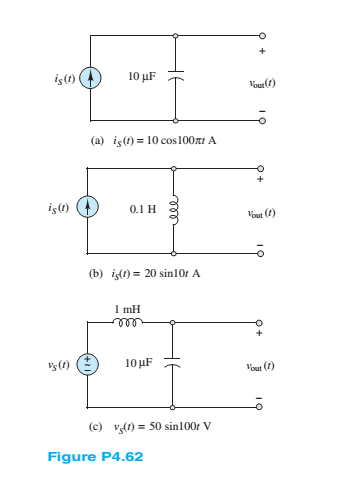
Chapter 4, Problem 4.62HP
Find the sinusoidal steady-state output
Expert Solution & Answer
Want to see the full answer?
Check out a sample textbook solution
Students have asked these similar questions
NO AI PLEASE
NO AI PLEASE
Add a second start button to the basic circuit so Start Button 1 or Start Button 2 can be used to start a motor. Include a second stop button that is connected so that Stop Button 1 or Start Button 2 can be used to stop the motor.
Chapter 4 Solutions
Principles and Applications of Electrical Engineering
Ch. 4 - The current through a 0.8-H inductor is given by...Ch. 4 - For each case shown below, derive the expression...Ch. 4 - Derive the expression for the voltage across...Ch. 4 - In the circuit shown in Figure P4.4, assume R=1...Ch. 4 - Prob. 4.5HPCh. 4 - In the circuit shown in Figure P4.4, assume R=2...Ch. 4 - In the circuit shown in Figure P4.7, assume R=2...Ch. 4 - Prob. 4.8HPCh. 4 - Prob. 4.9HPCh. 4 - Prob. 4.10HP
Ch. 4 - The voltage waveform shown in Figure P4.10 is...Ch. 4 - The voltage across a 0.5-mH inductor, Plotted as a...Ch. 4 - Prob. 4.13HPCh. 4 - The current through a 16-H inductor is zero at t=0...Ch. 4 - The voltage across a generic element X has the...Ch. 4 - The plots shown in Figure P4.16 are the voltage...Ch. 4 - The plots shown in Figure P4.17 are the voltage...Ch. 4 - The plots shown in Figure P4.18 are the voltage...Ch. 4 - The plots shown in Figure P4.19 are the voltage...Ch. 4 - The voltage vL(t) across a 10-mH inductor is shown...Ch. 4 - The current through a 2-H inductor is p1otted in...Ch. 4 - Prob. 4.22HPCh. 4 - Prob. 4.23HPCh. 4 - Prob. 4.24HPCh. 4 - The voltage vC(t) across a capacitor is shown in...Ch. 4 - The voltage vL(t) across an inductor is shown in...Ch. 4 - Find the average and rms values of x(t) when:...Ch. 4 - The output voltage waveform of a controlled...Ch. 4 - Refer to Problem 4.28 and find the angle + that...Ch. 4 - Find the ratio between the average and rms value...Ch. 4 - The current through a 1- resistor is shown in...Ch. 4 - Derive the ratio between the average and rms value...Ch. 4 - Find the rms value of the current waveform shown...Ch. 4 - Determine the rms (or effective) value of...Ch. 4 - Assume steady-state conditions and find the energy...Ch. 4 - Assume steady-state conditions and find the energy...Ch. 4 - Find the phasor form of the following functions:...Ch. 4 - Convert the following complex numbers to...Ch. 4 - Convert the rectangular factors to polar form and...Ch. 4 - Complete the following exercises in complex...Ch. 4 - Convert the following expressions to rectangular...Ch. 4 - Find v(t)=v1(t)+v2(t) where...Ch. 4 - The current through and the voltage across a...Ch. 4 - Express the sinusoidal waveform shown in Figure...Ch. 4 - Prob. 4.45HPCh. 4 - Convert the following pairs of voltage and current...Ch. 4 - Determine the equivalent impedance seen by the...Ch. 4 - Determine the equivalent impedance seen by the...Ch. 4 - The generalized version of Ohm’s law for impedance...Ch. 4 - Prob. 4.50HPCh. 4 - Determine the voltage v2(t) across R2 in the...Ch. 4 - Determine the frequency so that the current Ii...Ch. 4 - Prob. 4.53HPCh. 4 - Use phasor techniques to solve for the current...Ch. 4 - Use phasor techniques to solve for the voltage...Ch. 4 - Prob. 4.56HPCh. 4 - Solve for VR shown in Figure P4.57. Assume:...Ch. 4 - With reference to Problem 4.55, find the value of ...Ch. 4 - Find the current iR(t) through the resistor shown...Ch. 4 - Find vout(t) shown in Figure P4.60.Ch. 4 - Find the impedance Z shown in Figure...Ch. 4 - Find the sinusoidal steady-state output vout(t)...Ch. 4 - Determine the voltage vL(t) across the inductor...Ch. 4 - Determine the current iR(t) through the resistor...Ch. 4 - Find the frequency that causes the equivalent...Ch. 4 - a. Find the equivalent impedance Zo seen by the...Ch. 4 - A common model for a practical capacitor has...Ch. 4 - Using phasor techniques, solve for vR2 shown in...Ch. 4 - Using phasor techniques to solve for iL in the...Ch. 4 - Determine the Thévenin equivalent network seen by...Ch. 4 - Determine the Norton equivalent network seen by...Ch. 4 - Use phasor techniques to solve for iL(t) in...Ch. 4 - Use mesh analysis to determine the currents i1(t)...Ch. 4 - Prob. 4.74HPCh. 4 - Prob. 4.75HPCh. 4 - Find the Thévenin equivalent network seen by the...Ch. 4 - Prob. 4.77HPCh. 4 - Prob. 4.78HPCh. 4 - Prob. 4.79HPCh. 4 - Prob. 4.80HPCh. 4 - Use mesh analysis to find the phasor mesh current...Ch. 4 - Write the node equations required to solve for all...Ch. 4 - Determine Vo in the circuit of Figure...Ch. 4 - Prob. 4.84HP
Knowledge Booster


Learn more about
Need a deep-dive on the concept behind this application? Look no further. Learn more about this topic, electrical-engineering and related others by exploring similar questions and additional content below.Similar questions
- Add a second start button to the basic circuit so Start Button 1 or Start Button 2 can be used to start a motor. Include a second stop button that is connected so that Stop Button 1 or Start Button 2 can be used to stop the motor.arrow_forwardCircuit Logic. Match each statement to the proper circuit. All circuits have been drawn with a light (L) to represent the load, whether it is a motor, bell, or any other kind of load. In addition, each switch is illustrated as a pushbutton whether it is a maintained switch, momentary switch, pushbutton, switch-on target, or any other type of switch. from electrical motor controls for integrated systems workbook 2014 chapter 5arrow_forwardAssume ideal op-amp. If V_DC= 2.9, find I_L in mAarrow_forward
- R is 12 kΩ . Find the Thevenin equivalent resistance.arrow_forwardAssuming an ideal op-amp, design an inverting amplifier with a gain of 25 dB having the largest possible input resistance under the constraint of having to use resistors no larger than 90 kΩ. What's the input resist?arrow_forwardI need help with this problem and an explanation of the solution for the image described below. (Introduction to Signals and Systems)arrow_forward
- I hope the solution is on paper and not artificial intelligence. The subject is control systemarrow_forwardI hope the solution is on paper and not artificial intelligence.arrow_forwardVs R1 R2 ww ww 21x R3 Define the Thevenin equivalent of the above circuit where R1= 10 52, R2= 30 S2, R3 = 30 12, Vs = 70 V. VThevenin Number V RThevenin = Number Ωarrow_forward
arrow_back_ios
SEE MORE QUESTIONS
arrow_forward_ios
Recommended textbooks for you
 Introductory Circuit Analysis (13th Edition)Electrical EngineeringISBN:9780133923605Author:Robert L. BoylestadPublisher:PEARSON
 Delmar's Standard Textbook Of ElectricityElectrical EngineeringISBN:9781337900348Author:Stephen L. HermanPublisher:Cengage Learning
 Programmable Logic ControllersElectrical EngineeringISBN:9780073373843Author:Frank D. PetruzellaPublisher:McGraw-Hill Education
 Fundamentals of Electric CircuitsElectrical EngineeringISBN:9780078028229Author:Charles K Alexander, Matthew SadikuPublisher:McGraw-Hill Education
 Electric Circuits. (11th Edition)Electrical EngineeringISBN:9780134746968Author:James W. Nilsson, Susan RiedelPublisher:PEARSON
 Engineering ElectromagneticsElectrical EngineeringISBN:9780078028151Author:Hayt, William H. (william Hart), Jr, BUCK, John A.Publisher:Mcgraw-hill Education,
Introductory Circuit Analysis (13th Edition)
Electrical Engineering
ISBN:9780133923605
Author:Robert L. Boylestad
Publisher:PEARSON
Delmar's Standard Textbook Of Electricity
Electrical Engineering
ISBN:9781337900348
Author:Stephen L. Herman
Publisher:Cengage Learning
Programmable Logic Controllers
Electrical Engineering
ISBN:9780073373843
Author:Frank D. Petruzella
Publisher:McGraw-Hill Education
Fundamentals of Electric Circuits
Electrical Engineering
ISBN:9780078028229
Author:Charles K Alexander, Matthew Sadiku
Publisher:McGraw-Hill Education
Electric Circuits. (11th Edition)
Electrical Engineering
ISBN:9780134746968
Author:James W. Nilsson, Susan Riedel
Publisher:PEARSON
Engineering Electromagnetics
Electrical Engineering
ISBN:9780078028151
Author:Hayt, William H. (william Hart), Jr, BUCK, John A.
Publisher:Mcgraw-hill Education,
Capacitors Explained - The basics how capacitors work working principle; Author: The Engineering Mindset;https://www.youtube.com/watch?v=X4EUwTwZ110;License: Standard YouTube License, CC-BY