Materials for Civil and Construction Engineers (4th Edition)
4th Edition
ISBN: 9780134320533
Author: Michael S. Mamlouk, John P. Zaniewski
Publisher: PEARSON
expand_more
expand_more
format_list_bulleted
Textbook Question
Chapter 4, Problem 4.17QP
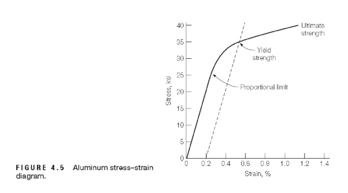
Referring to Figure 4.5, determine approximate values of the following:
a. modulus of elasticity
b. proportional limit
c. yield strength at a strain offset of 0.002
d. tangential modulus at a stress of 33 ksi
e. secant modulus at a stress of 33 ksi

Expert Solution & Answer
Want to see the full answer?
Check out a sample textbook solution
Students have asked these similar questions
How many custom bricks of size 3 1/4 x 3 3/4 x 11 7/8 inches are there per square foot of wall area when the mortar joint
is 1/4
Given a circular curve connecting 2 tangents that intersect at an angle of 55°. The PI is at thestation (948+50) and the design speed of the highway is 70 mi/h. Determine:(a) stations of the PC and PT(c) Deflection angles and chord lengths for the first, middle, and last chords
A simple circular curve exists with a radius of 900 ft connects the tangents of a two-lanehighway that has a posted speed limit of 45 mph. The highway curve is not superelevated,e=0. A structure is proposed on land on the inside of the curve. Assume the road is on a levelgrade. Determine the minimum distance allowable between the proposed structure and thecenterline of the curve such that the current maximum safe speed of the curve would notneed to be reduced
Chapter 4 Solutions
Materials for Civil and Construction Engineers (4th Edition)
Ch. 4 - Name the two primary factors that make aluminum an...Ch. 4 - Prob. 4.2QPCh. 4 - An aluminum alloy specimen with a radius of 0.28...Ch. 4 - An aluminum alloy bar with a radius of 7 mm was...Ch. 4 - Decode the characteristics of a 6063 T831...Ch. 4 - A round aluminum alloy bar with a 0.6 in. diameter...Ch. 4 - An aluminum alloy bar with a rectangular cross...Ch. 4 - A round aluminum alloy bar with a 0.25-in....Ch. 4 - An aluminum alloy rod has a circular cross section...Ch. 4 - An aluminum alloy cylinder with a diameter of 3...
Ch. 4 - A 3003-H14 aluminum alloy rod with 0.5 in....Ch. 4 - The stressstrain relation of an aluminum alloy bar...Ch. 4 - An aluminum specimen originally 300 mm long is...Ch. 4 - A tension stress of 40 ksi was applied on a 12-in....Ch. 4 - A tension test was performed on an aluminum alloy...Ch. 4 - In Problem 4.15, plot the stressstrain...Ch. 4 - Referring to Figure 4.5, determine approximate...Ch. 4 - Prob. 4.18QPCh. 4 - A tensile stress is applied along the long axis of...Ch. 4 - A cylindrical aluminum alloy rod with a 0.5 in....Ch. 4 - Prob. 4.21QPCh. 4 - Discuss galvanic corrosion of aluminum. How can...
Knowledge Booster
Learn more about
Need a deep-dive on the concept behind this application? Look no further. Learn more about this topic, civil-engineering and related others by exploring similar questions and additional content below.Similar questions
- A +4.4% grade intersects with a -3.3% grade at a station (550+30) at an elevation of400 ft. If the design speed is 60 mi/h, determine:(a) the minimum length of the vertical curve using the rate of vertical curvature(b) the stations and elevations of the BVC and EVC(c) the tangent and curve elevations of BVC, full stations, and EVC(d) the station and elevation of the highest pointarrow_forwardDetermine the minimum length of a sag vertical curve if the grades are –3% and +4%. The design speed is 75 mi/h. State all assumptions used. Make sure to consider the following criteria: stopping sight distance, comfort, and general appearancearrow_forwardQuestion 6: Chlorine is widely used to purify municipal water supplies and to treat swimming pool waters. Suppose that the volume of a particular sample of Cl₂ gas is 8.70 L at 895 torr and 24°C. (a) How many grams of Cl₂ are in the sample? ⚫ Atomic mass of CI = 35.453 g/mol • Molar mass of Cl₂ = 2 x 35.453 = 70.906 g/mol Solution: Use the Ideal Gas Law: Step 1: Convert Given Values • Pressure: P = 895 torr → atm PV= = nRT 1 P = 895 × = 1.1789 atm 760 • Temperature: Convert to Kelvin: T24273.15 = 297.15 K • Gas constant: R = 0.0821 L atm/mol. K Volume: V = 8.70 L Step 2: Solve for n . PV n = RT n = (1.1789)(8.70) (0.0821)(297.15) 10.25 n = = 0.420 mol 24.405 Step 3: Calculate Mass of Cl₂ Final Answer: 29.78 g of Cl₂. mass nx M mass= (0.420)(70.906) mass= 29.78 garrow_forward
- Please solve the highlighted question.arrow_forward1. Design a PVC sanitary sewer collection system for the Village of Waffle (Figure P-17-24 B, shown below) by preparing a sewer design table similar to that shown in Example 19-2 and a profile drawing similar to Figure 19-13b B. You only need to show the calculations for the pipes running along Bacon Road and Eggs Road, starting at point F and ending at Point B in the figure below. Your design should comply with the requirements specified in Chapter 30 of the 10 States Standards for Wastewater. Use the following assumptions: 0 о о Average daily flow rate is the same as average daily water demand, 9.2 m³/hr Peaking factor for peak dry weather flow is 6.2 Peak wet weather flow is equal to the peak dry weather flow plus an assumption for infiltration and inflow at 40 L/d-mm-km of pipe DODO on Ro 450 m 28 m D. 150 m Apartments D 400 m D 200 m B 250 m 0 Dogs Road ROOD625 m -120 m Syrup River 120 m 100-Year flood Point Elevation Tank 137.0 m A 130.0 m B 122.0 m C 122.3 m D 122.6 m A D 300 m…arrow_forwardNeed helparrow_forward
- 2. Design a circular clarifier for a flow rate of 34,560 m³/d. Use a design overflow rate of 30 m³/d-m². Assume the clarifier has a center feed and a side water depth of 4.3 m. Use a feedwell detention time of 20 min. Provide the following information to support your design: • Diameter of the clarifier • Diameter and depth of the feedwell . Check the flow velocity across the sludge zone • Calculate the weir loading ratearrow_forwardName: Course: Mechanics of Deformable Bodies Investigation and Design of Axially Loaded Structural Members Date: Term: A. Objective 1. To be able to determine internal axial load on structural members 2. To be able to design structural members with axial internal reactions B. General Instruction 1. Write your solution legibly in separate sheets of clean bond paper. 2. Box your final answer in your solution. C. Situation A truss structure is an assembly of straight structural members that form triangular panels. The assembly of triangular panels makes the truss establish a rigid configuration. In a truss structure, connections are theoretically assumed to act as smooth pin; therefore, it does not resist any moment or bending. Due to this magnificent behavior, truss members only resist axial forces in the design phase that could either be compressive or tensile. Presented in the figure is a truss that is a component of a roof framing system to be constructed at the University Lucena City…arrow_forward1- A two-lane highway (two 3.6 m lanes) has a posted speed limit of 100 km/h and, on one section, has both horizontal and vertical curves, as shown in the figure below. A recent daytime crash (driver traveling westbound and striking a stationary roadway object) resulted in a fatality and a lawsuit alleging that the 100 km/h posted speed limit is an unsafe speed for the curves in question and was a major cause of the crash. Evaluate and comment on the roadway design (after Mannering and Washburn). Plan view (horizontal alignment) PC Station 4+90 Profile view (vertical alignment) e = 8.0% 100 m Sight obstruction 50° G₁ = -2.0% PVC Station 4+30 T PVI PVT Station 6+80 PT N Station 10+00 G₂ = +4.0%arrow_forward
- Existing Filter Design Parameters at 22.5 MGD: A) # of Filters: 5 B) #Bays per Filter: 1 C) Bay Surface Dimensions (L X W X D): (40.5 ft. X 13 ft. X 11.5 ft.) D) Surface Area per Filter: 526.5 ft^2 E) Total Filtration Area: 2,633 ft^2 F) Hydraulic Loading Rate: 6 gpm/sf (w/ all filters in service) G) Filtration Capacity at HLR: 22.7 MGD H) Filter Media: 1) Anthracite: 20 in. depth, 1.00 mm Effective Size 2) Sand: 9 in. depth, 0.50 mm Effective Size 1) L/d Ratio (depth of media/effective size): 965 J) Backwash Pumps: 15 MGD (two pumps) K) Backwash water for the filters is provided from the high service pump station through a 24-inch backwash water L) Air Wash Blowers: 1) Number: 2 Hoffman Centrifugal Model 38406A, 125 hp 2) Capacity: 3,100 scfm (standard cubic ft/^2) 3) Air Scour Rate: 5.90 scfm/ft^2 Deliverables: 1) Determine if the existing filtration system is sufficient to accommodate the projected future capacity. A) Current Capacity: 22.5 MGD B) Future Capacity: 34.5 MGD for…arrow_forwardPart 1: True or False. Indicate whether the following statements are True (T) or False (F) by encircling the letter that corresponds to your answer. 1. (T/F) Residual soils are formed by the weathering of rocks in place. 2. (T/F) The Standard Penetration Test (SPT) provides a disturbed soil sample. 3. (T/F) The groundwater table has no effect on the interpretation of soil exploration data. 4. (T/F) Geophysical methods are always more accurate than direct soil sampling methods. 5. (T/F) The N-value in the SPT is the number of blows required to drive the sampler the first 150 mm. Part 2: Multiple choice. Choose the best answer for each question. 1. Which of the following is NOT a transported soil deposit? a) Alluvial b) Glacial c) Residual d) Aeolian 2. What is the primary purpose of subsurface exploration? a) To determine the depth of bedrock b) To identify soil types and their properties 3. Which test provides a continuous profile of soil a) Standard Penetration Test (SPT) b) Cone…arrow_forwardDetermin the shear and moment in teh beam as a function of x where 2m<x<4m.arrow_forward
arrow_back_ios
SEE MORE QUESTIONS
arrow_forward_ios
Recommended textbooks for you
 Steel Design (Activate Learning with these NEW ti...Civil EngineeringISBN:9781337094740Author:Segui, William T.Publisher:Cengage Learning
 Materials Science And Engineering PropertiesCivil EngineeringISBN:9781111988609Author:Charles GilmorePublisher:Cengage Learning
 Construction Materials, Methods and Techniques (M...Civil EngineeringISBN:9781305086272Author:William P. Spence, Eva KultermannPublisher:Cengage Learning
 Principles of Foundation Engineering (MindTap Cou...Civil EngineeringISBN:9781337705028Author:Braja M. Das, Nagaratnam SivakuganPublisher:Cengage Learning
 Fundamentals of Geotechnical Engineering (MindTap...Civil EngineeringISBN:9781305635180Author:Braja M. Das, Nagaratnam SivakuganPublisher:Cengage Learning
 Engineering Fundamentals: An Introduction to Engi...Civil EngineeringISBN:9781305084766Author:Saeed MoaveniPublisher:Cengage Learning

Steel Design (Activate Learning with these NEW ti...
Civil Engineering
ISBN:9781337094740
Author:Segui, William T.
Publisher:Cengage Learning

Materials Science And Engineering Properties
Civil Engineering
ISBN:9781111988609
Author:Charles Gilmore
Publisher:Cengage Learning

Construction Materials, Methods and Techniques (M...
Civil Engineering
ISBN:9781305086272
Author:William P. Spence, Eva Kultermann
Publisher:Cengage Learning

Principles of Foundation Engineering (MindTap Cou...
Civil Engineering
ISBN:9781337705028
Author:Braja M. Das, Nagaratnam Sivakugan
Publisher:Cengage Learning

Fundamentals of Geotechnical Engineering (MindTap...
Civil Engineering
ISBN:9781305635180
Author:Braja M. Das, Nagaratnam Sivakugan
Publisher:Cengage Learning

Engineering Fundamentals: An Introduction to Engi...
Civil Engineering
ISBN:9781305084766
Author:Saeed Moaveni
Publisher:Cengage Learning
Material Properties 101; Author: Real Engineering;https://www.youtube.com/watch?v=BHZALtqAjeM;License: Standard YouTube License, CC-BY