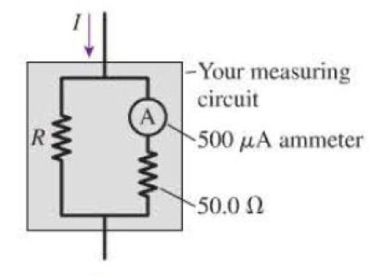
Problem 1CQ: The tip of a flashlight bulb is touching the top of a 3 V battery as shown in Figure Q23.1. Does the... Problem 2CQ: A flashlight bulb is connected to a battery and is glowing; the circuit is shown in Figure Q23.2. Is... Problem 3CQ: Current Iin flows into three resistors connected together one after the other as shown in Figure... Problem 4CQ: The circuit in Figure Q23.4 has two resistors, with R1 R2. Which resistor dissipates the larger... Problem 5CQ: The circuit in Figure Q23.5 has a battery and two resistors, with R1 R2. Which resistor dissipates... Problem 6CQ: In the circuit shown in Figure Q23.6, bulbs A and B are glowing. Then the switch is closed. What... Problem 7CQ: Figure Q23.7 shows two circuits. The two batteries are identical and the four resistors all have... Problem 8CQ: Figure Q23.8 shows two circuits. The two batteries are identical and the four resistors all have... Problem 9CQ: a. In Figure Q23.9, what fraction of current I goes through the 3 resistor? If the 9 resistor is... Problem 10CQ: Two of the three resistors in Figure Q23.10 are unknown but equal. Is the total resistance between... Problem 11CQ: Two of the three resistors in Figure Q23.11 are unknown but equal. Is the resistance between points... Problem 12CQ: Rank in order, from largest to smallest, the currents I1, I2, and I3 in the circuit diagram in... Problem 13CQ: The three bulbs in Figure Q23.13 are identical. Rank the bulbs from brightest to dimmest. Explain.... Problem 14CQ: The four bulbs in Figure Q23.14 are identical. Rank the bulbs from brightest to dimmest. Explain.... Problem 15CQ: Figure Q23.15 shows five identical bulbs connected to a battery. All the bulbs are glowing. Rank the... Problem 16CQ: a. The three bulbs in Figure Q23.16 are identical. Rank the bulbs from brightest to dimmest.... Problem 17CQ: Initially, bulbs A and B in Figure Q23.17 are both glowing. Bulb B is then removed from its socket.... Problem 18CQ: a. Consider the points a and b in Figure Q23.18. Is the potential difference Vab between points a... Problem 19CQ: When the switch in Figure Q23.19 is closed, a. Does the current through the battery increase,... Problem 20CQ: A voltmeter is (incorrectly) inserted into a circuit as shown in Figure Q23.20. a. What is the... Problem 21CQ: An ammeter is (incorrectly) inserted into a circuit as shown in Figure Q23.21. a. What is the... Problem 22CQ: Rank in order, from largest to smallest, the equivalent capacitances (Ceq)1 to (Ceq))4 of the four... Problem 23CQ: Figure Q23.23 shows a circuit consisting of a battery, a switch, two identical lightbulbs, and a... Problem 24CQ: Figure Q23.24 shows the volt age as a function of time across a capacitor as it is discharged... Problem 25CQ: A charged capacitor could be connected to two identical resistors in either of the two ways shown in... Problem 26CQ: A flashing light is controlled by the charging and discharging of an RC circuit. If the light is... Problem 27CQ: A device to make an electrical measurement of skin moisture has electrodes that form two plates of a... Problem 28CQ: Consider the model of nerve conduction in myelinated axons presented in the chapter. Suppose the... Problem 29CQ: Adding a myelin sheath to an axon results in faster signal propagation. It also means that less... Problem 30MCQ: What is the current in the circuit of Figure Q23.30? A. 1.0 A B. 1.7 A C. 2.5 A D. 4.2 A Figure... Problem 31MCQ: Which resistor in Figure Q23.30 dissipates the most power? A. The 4.0 resistor. B. The 6.0 ... Problem 32MCQ: Normally, household lightbulbs are connected in parallel to a power supply. Suppose a 40 W and a 60... Problem 33MCQ: A metal wire of resistance R is cut into two pieces of equal length. The two pieces are connected... Problem 34MCQ: What is the value of resistor R in Figure Q23.34? A. 4.0 B. 12 C. 36 D. 72 e. 96 Figure Q23.34 Problem 35MCQ: Two capacitors are connected in series. They are then reconnected to be in parallel. The capacitance... Problem 36MCQ: If a cells membrane thickness doubles but the cell stays the same size, how do the resistance and... Problem 37MCQ: If a cells diameter is reduced by 50% without changing the membrane thickness, how do the resistance... Problem 1P: Draw a circuit diagram tor the circuit of Figure P23.1. Figure P23.1 Problem 2P: Draw a circuit diagram for the circuit of Figure P23.2. Figure P23.2 Problem 3P: Draw a circuit diagram for the circuit of Figure P23.3. Figure P23.3 Problem 4P: In Figure P23.4, what is the current in the wire above the junction? Does charge How toward or away... Problem 5P: The lightbulb in the circuit diagram of Figure P23.5 has a resistance of 1.0 . Consider the... Problem 6P: a. What are the magnitude and direction of the current in the 30 resistor in Figure P23.6? b. Draw... Problem 7P: a. What are the magnitude and direction of the current in the 18 resistor in Figure P23.7? b. Draw... Problem 8P: a. What is the potential difference across each resistor in Figure P23.8? b. Draw a graph of the... Problem 9P: The current in a circuit with only one battery is 2.0 A. Figure P23.9 shows how the potential... Problem 10P: What is the equivalent resistance of each group of resistors shown in Figure P23.10? Figure P23.10 Problem 11P: What is the equivalent resistance of each group of resistors shown in Figure P23.11? Figure P23.11 Problem 12P Problem 13P Problem 14P: You have a collection of 1.0 k resistors. How can you connect four of them to produce an equivalent... Problem 15P: You have a collection of six 1.0 k resistors. What is the smallest resistance you can make by... Problem 16P: You have six 1.0 k resistors. How can you connect them to produce a total equivalent resistance of... Problem 17P: What is the equivalent resistance between points a and b in Figure P23.17? Figure P23.17 Problem 18P: What is the equivalent resistance between points a and b in Figure P23.18? Figure P23.18 Problem 19P: The currents in two resistors in a circuit are shown in Figure P23.19. What is the value of resistor... Problem 20P: Two batteries supply current to the circuit in Figure P23.20. The figure shows the potential... Problem 21P: Part of a circuit is shown in Figure P23.21. a. What is the current through the 3.0 resistor? b.... Problem 22P: What is the value of resistor R in Figure P23.22? Figure P23.22 Problem 23P: What are the resistances R and the emf of the battery in Figure P23.23? Figure P23.23 Problem 24P: The ammeter in Figure P23.24 reads 3.0 A. Find I1, I2, and . Figure P23.24 Problem 25P: Find the current through and the potential difference across each resistor in Figure P23.25. Figure... Problem 26P: Find the current through and the potential difference across each resistor in Figure P23.26. Figure... Problem 27P: For the circuit shown in Figure P23.27, find the current through and the potential difference across... Problem 28P: Consider the potential differences between pairs of points in Figure P23.28. What are the magnitudes... Problem 29P: For the circuit shown in Figure P23.29, find the current through and the potential difference across... Problem 30P: A photoresistor, whose resistance decreases with light intensity, is connected in the circuit of... Problem 31P: The two unknown resistors in Figure P23.31 have the same resistance R. When the switch is closed,... Problem 32P: A 6.0 F capacitor, a 10 F capacitor, and a 16 F capacitor are connected in parallel. What is their... Problem 33P: A 6.0 F capacitor, a 10 F capacitor, and a 16 F capacitor are connected in series. What is their... Problem 34P: You need a capacitance of 50 F, but you dont happen to have a 50 F capacitor. You do have a 30 F... Problem 35P: You need a capacitance of 50 F, but you dont happen to have a 50 F capacitor. You do have a 75 F... Problem 36P: What is the equivalent capacitance of the three capacitors in Figure P23.36? Figure P23.36 Problem 37P: What is the equivalent capacitance of the three capacitors in Figure P23.37? Figure P23.37 Problem 38P: For the circuit of Figure P23.38, a. What is the equivalent capacitance? b. How much charge flows... Problem 39P: For the circuit of Figure P23.39. a. What is the equivalent capacitance? b. What is the charge of... Problem 40P: What is the time constant for the discharge of the capacitor in Figure P23.40? Figure P23.40 Problem 41P: What is the time constant for the discharge of the capacitor Figure P23.41? Figure P23.41 Problem 42P: After how many time constants has the voltage across a discharging capacitor decayed to 0.10% of its... Problem 43P: A 10F capacitor initially charged to 20C is discharged through a 1.0 k resistor. How long does it... Problem 44P: A capacitor charging circuit consists of a battery, an uncharged 20 F capacitor, and a 4.0 k... Problem 45P: The switch in Figure P23.45 has been in position a for a long time. It is changed to position b at t... Problem 46P: A 9.0-nm-thick cell membrane undergoes an action potential that follows the curve in the table on... Problem 47P: A cell membrane has a resistance and a capacitance and thus a characteristic time constant. What is... Problem 48P: Changing the thickness of the myelin sheath surrounding an axon changes its capacitance and thus the... Problem 49P: A particular myelinated axon has nodes spaced 0.80 mm apart. The resistance between nodes is 20 M;... Problem 50P: To measure signal propagation in a nerve in the arm, the nerve is triggered near the armpit. The... Problem 51P: A myelinated axon conducts nerve impulses at a speed of 40 m/s. What is the signal speed if the... Problem 52GP: How much power is dissipated by each resistor in Figure P23.52? Figure P23.52 Problem 53GP: Two 75 W (120 V) lightbulbs are wired in series, then the combination is connected to a 120 V... Problem 54GP: The corroded contacts in a lightbulb socket have 5.0 total resistance. How much actual power is... Problem 55GP: A real battery is not just an emf. We can If model a real 1.5 V battery as a 1.5 V emf in series... Problem 56GP: For the real battery shown in Figure P23.55, calculate the power dissipated by a resistor R... Problem 57GP: Batteries are recharged by connecting them to a power supply (i.e., another battery) of greater emf... Problem 58GP: When two resistors are connected in parallel across a battery of unknown voltage, one resistor... Problem 59GP: The 10 resistor in Figure P23.59 is dissipating 40 W of power. How much power are the other two... Problem 60GP: At this instant the current in the circuit of Figure P23.60 is 20 mA in the direction shown and the... Problem 61GP: What is the equivalent resistance between points a and b in Figure P23.61? Figure P23.61 Problem 62GP: What is the current through the battery in Figure P23.62 when the switch is (a) open and (b) closed?... Problem 63GP: What is the ratio P parallel/P series of the total power dissipated by two identical resistors... Problem 64GP: You have a device that needs a voltage reference of 3.0 V, but you have only a 9.0 V battery.... Problem 65GP: There is a current of 0.25 A in the circuit of Figure P23.65. a. What is the direction of the... Problem 66GP: A circuit youre building needs an ammeter that goes from 0 mA to a full-scale reading of 50.0 mA.... Problem 67GP: A circuit youre building needs a voltmeter that goes from V to a full-scale reading of 5.0 V.... Problem 68GP: For the circuit shown in Figure P23.68, find the current through and the potential difference across... Problem 69GP: You have three 12 F capacitors. Draw diagrams showing how you could arrange all three so that their... Problem 70GP: Initially, the switch in Figure P23.70 is in position a and capacitors C2 and C3 are uncharged. Then... Problem 71GP: The capacitor in an RC circuit with a time constant of 15 ms is charged to 10 V. The capacitor... Problem 72GP: The capacitor in Figure P23.72 is initially uncharged and the switch, in position c, is not... Problem 73GP: What value resistor will discharge a 1.0 F capacitor to 10% of its initial charge in 2.0 ms? Problem 74GP: The charging circuit for the flash system of a camera uses a 100 F capacitor that is charged from a... Problem 75GP: A capacitor is discharged through a 100 resistor. The discharge current decreases to 25% of its... Problem 76GP: A 50 /F capacitor that had been charged to 30 V is discharged through a resistor. Figure P23.76... Problem 77GP: The switch in Figure P23.77 has been closed for a very long time. a. What is the charge on the... Problem 78GP: Intermittent windshield wipers use a variable resistor in an RC circuit to set the delay between... Problem 79GP: In Example 23.14 we estimated the capacitance of the cell membrane to be 89 pF, and in Example 23.15... Problem 80GP: The giant axon of a squid is 0.5 mm in diameter, 10 cm long, and not myelinated. Unmyelinated cell... Problem 81GP: A cell has a 7.0-nm-thick membrane with a total membrane area of 6.0 109 m2. a. We can model the... Problem 82MSPP: The Defibrillator A defibrillator is designed to pass a large current through a patients torso in... Problem 83MSPP: The Defibrillator A defibrillator is designed to pass a large current through a patients torso in... Problem 84MSPP: The Defibrillator A defibrillator is designed to pass a large current through a patients torso in... Problem 85MSPP: A defibrillator is designed to pass a large current through a patients torso in order to stop... Problem 86MSPP: The voltage produced by a single nerve or muscle cell is quite small, but there are many species of... Problem 87MSPP: The voltage produced by a single nerve or muscle cell is quite small, but there are many species of... Problem 88MSPP: The voltage produced by a single nerve or muscle cell is quite small, but there are many species of... Problem 89MSPP: The voltage produced by a single nerve or muscle cell is quite small, but there are many species of... format_list_bulleted


 Principles of Physics: A Calculus-Based TextPhysicsISBN:9781133104261Author:Raymond A. Serway, John W. JewettPublisher:Cengage Learning
 Physics for Scientists and Engineers: Foundations...PhysicsISBN:9781133939146Author:Katz, Debora M.Publisher:Cengage Learning
 Physics for Scientists and EngineersPhysicsISBN:9781337553278Author:Raymond A. Serway, John W. JewettPublisher:Cengage Learning
 Physics for Scientists and Engineers with Modern ...PhysicsISBN:9781337553292Author:Raymond A. Serway, John W. JewettPublisher:Cengage Learning
 College PhysicsPhysicsISBN:9781305952300Author:Raymond A. Serway, Chris VuillePublisher:Cengage Learning
 College PhysicsPhysicsISBN:9781285737027Author:Raymond A. Serway, Chris VuillePublisher:Cengage Learning