College Physics: A Strategic Approach (3rd Edition)
3rd Edition
ISBN: 9780321879721
Author: Randall D. Knight (Professor Emeritus), Brian Jones, Stuart Field
Publisher: PEARSON
expand_more
expand_more
format_list_bulleted
Videos
Textbook Question
Chapter 23, Problem 62GP
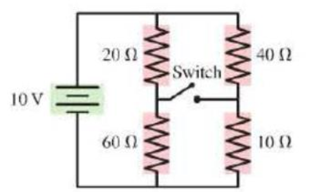
What is the current through the battery in Figure P23.62 when the switch is (a) open and (b) closed?
Figure P23.62
Expert Solution & Answer
Want to see the full answer?
Check out a sample textbook solution
Students have asked these similar questions
You are working with a team that is designing a new roller coaster-type amusement park ride for a major theme park. You are present for the testing of the ride, in which an empty 150 kg car is sent along the entire ride. Near the end of the ride, the car is at near rest at the top of a 100 m
tall track. It then enters a final section, rolling down an undulating hill to ground level. The total length of track for this final section from the top to the ground is 250 m. For the first 230 m, a constant friction force of 370 N acts from computer-controlled brakes. For the last 20 m, which is
horizontal at ground level, the computer increases the friction force to a value required for the speed to be reduced to zero just as the car arrives at the point on the track at which the passengers exit.
(a) Determine the required constant friction force (in N) for the last 20 m for the empty test car.
N
(b) Find the highest speed (in m/s) reached by the car during the final section of track length…
A player kicks a football at the start of the game. After a 4 second flight, the ball touches the ground 50 m from the kicking tee. Assume air resistance is negligible and the take-off and landing height are the same (i.e., time to peak = time to fall = ½ total flight time). (Note: For each question draw a diagram to show the vector/s. Show all the step and provide units in the answers. Provide answer to 2 decimal places unless stated otherwise.) Calculate and answer all parts. Only use equations PROVIDED:
Please answer.
Chapter 23 Solutions
College Physics: A Strategic Approach (3rd Edition)
Ch. 23 - The tip of a flashlight bulb is touching the top...Ch. 23 - A flashlight bulb is connected to a battery and is...Ch. 23 - Current Iin flows into three resistors connected...Ch. 23 - The circuit in Figure Q23.4 has two resistors,...Ch. 23 - The circuit in Figure Q23.5 has a battery and two...Ch. 23 - In the circuit shown in Figure Q23.6, bulbs A and...Ch. 23 - Figure Q23.7 shows two circuits. The two batteries...Ch. 23 - Figure Q23.8 shows two circuits. The two batteries...Ch. 23 - a. In Figure Q23.9, what fraction of current I...Ch. 23 - Two of the three resistors in Figure Q23.10 are...
Ch. 23 - Two of the three resistors in Figure Q23.11 are...Ch. 23 - Rank in order, from largest to smallest, the...Ch. 23 - The three bulbs in Figure Q23.13 are identical....Ch. 23 - The four bulbs in Figure Q23.14 are identical....Ch. 23 - Figure Q23.15 shows five identical bulbs connected...Ch. 23 - a. The three bulbs in Figure Q23.16 are identical....Ch. 23 - Initially, bulbs A and B in Figure Q23.17 are both...Ch. 23 - a. Consider the points a and b in Figure Q23.18....Ch. 23 - When the switch in Figure Q23.19 is closed, a....Ch. 23 - A voltmeter is (incorrectly) inserted into a...Ch. 23 - An ammeter is (incorrectly) inserted into a...Ch. 23 - Rank in order, from largest to smallest, the...Ch. 23 - Figure Q23.23 shows a circuit consisting of a...Ch. 23 - Figure Q23.24 shows the volt age as a function of...Ch. 23 - A charged capacitor could be connected to two...Ch. 23 - A flashing light is controlled by the charging and...Ch. 23 - A device to make an electrical measurement of skin...Ch. 23 - Consider the model of nerve conduction in...Ch. 23 - Adding a myelin sheath to an axon results in...Ch. 23 - What is the current in the circuit of Figure...Ch. 23 - Which resistor in Figure Q23.30 dissipates the...Ch. 23 - Normally, household lightbulbs are connected in...Ch. 23 - A metal wire of resistance R is cut into two...Ch. 23 - What is the value of resistor R in Figure Q23.34?...Ch. 23 - Two capacitors are connected in series. They are...Ch. 23 - If a cells membrane thickness doubles but the cell...Ch. 23 - If a cells diameter is reduced by 50% without...Ch. 23 - Draw a circuit diagram tor the circuit of Figure...Ch. 23 - Draw a circuit diagram for the circuit of Figure...Ch. 23 - Draw a circuit diagram for the circuit of Figure...Ch. 23 - In Figure P23.4, what is the current in the wire...Ch. 23 - The lightbulb in the circuit diagram of Figure...Ch. 23 - a. What are the magnitude and direction of the...Ch. 23 - a. What are the magnitude and direction of the...Ch. 23 - a. What is the potential difference across each...Ch. 23 - The current in a circuit with only one battery is...Ch. 23 - What is the equivalent resistance of each group of...Ch. 23 - What is the equivalent resistance of each group of...Ch. 23 - Prob. 12PCh. 23 - Prob. 13PCh. 23 - You have a collection of 1.0 k resistors. How can...Ch. 23 - You have a collection of six 1.0 k resistors. What...Ch. 23 - You have six 1.0 k resistors. How can you connect...Ch. 23 - What is the equivalent resistance between points a...Ch. 23 - What is the equivalent resistance between points a...Ch. 23 - The currents in two resistors in a circuit are...Ch. 23 - Two batteries supply current to the circuit in...Ch. 23 - Part of a circuit is shown in Figure P23.21. a....Ch. 23 - What is the value of resistor R in Figure P23.22?...Ch. 23 - What are the resistances R and the emf of the...Ch. 23 - The ammeter in Figure P23.24 reads 3.0 A. Find I1,...Ch. 23 - Find the current through and the potential...Ch. 23 - Find the current through and the potential...Ch. 23 - For the circuit shown in Figure P23.27, find the...Ch. 23 - Consider the potential differences between pairs...Ch. 23 - For the circuit shown in Figure P23.29, find the...Ch. 23 - A photoresistor, whose resistance decreases with...Ch. 23 - The two unknown resistors in Figure P23.31 have...Ch. 23 - A 6.0 F capacitor, a 10 F capacitor, and a 16 F...Ch. 23 - A 6.0 F capacitor, a 10 F capacitor, and a 16 F...Ch. 23 - You need a capacitance of 50 F, but you dont...Ch. 23 - You need a capacitance of 50 F, but you dont...Ch. 23 - What is the equivalent capacitance of the three...Ch. 23 - What is the equivalent capacitance of the three...Ch. 23 - For the circuit of Figure P23.38, a. What is the...Ch. 23 - For the circuit of Figure P23.39. a. What is the...Ch. 23 - What is the time constant for the discharge of the...Ch. 23 - What is the time constant for the discharge of the...Ch. 23 - After how many time constants has the voltage...Ch. 23 - A 10F capacitor initially charged to 20C is...Ch. 23 - A capacitor charging circuit consists of a...Ch. 23 - The switch in Figure P23.45 has been in position a...Ch. 23 - A 9.0-nm-thick cell membrane undergoes an action...Ch. 23 - A cell membrane has a resistance and a capacitance...Ch. 23 - Changing the thickness of the myelin sheath...Ch. 23 - A particular myelinated axon has nodes spaced 0.80...Ch. 23 - To measure signal propagation in a nerve in the...Ch. 23 - A myelinated axon conducts nerve impulses at a...Ch. 23 - How much power is dissipated by each resistor in...Ch. 23 - Two 75 W (120 V) lightbulbs are wired in series,...Ch. 23 - The corroded contacts in a lightbulb socket have...Ch. 23 - A real battery is not just an emf. We can If model...Ch. 23 - For the real battery shown in Figure P23.55,...Ch. 23 - Batteries are recharged by connecting them to a...Ch. 23 - When two resistors are connected in parallel...Ch. 23 - The 10 resistor in Figure P23.59 is dissipating 40...Ch. 23 - At this instant the current in the circuit of...Ch. 23 - What is the equivalent resistance between points a...Ch. 23 - What is the current through the battery in Figure...Ch. 23 - What is the ratio P parallel/P series of the total...Ch. 23 - You have a device that needs a voltage reference...Ch. 23 - There is a current of 0.25 A in the circuit of...Ch. 23 - A circuit youre building needs an ammeter that...Ch. 23 - A circuit youre building needs a voltmeter that...Ch. 23 - For the circuit shown in Figure P23.68, find the...Ch. 23 - You have three 12 F capacitors. Draw diagrams...Ch. 23 - Initially, the switch in Figure P23.70 is in...Ch. 23 - The capacitor in an RC circuit with a time...Ch. 23 - The capacitor in Figure P23.72 is initially...Ch. 23 - What value resistor will discharge a 1.0 F...Ch. 23 - The charging circuit for the flash system of a...Ch. 23 - A capacitor is discharged through a 100 resistor....Ch. 23 - A 50 /F capacitor that had been charged to 30 V is...Ch. 23 - The switch in Figure P23.77 has been closed for a...Ch. 23 - Intermittent windshield wipers use a variable...Ch. 23 - In Example 23.14 we estimated the capacitance of...Ch. 23 - The giant axon of a squid is 0.5 mm in diameter,...Ch. 23 - A cell has a 7.0-nm-thick membrane with a total...Ch. 23 - The Defibrillator A defibrillator is designed to...Ch. 23 - The Defibrillator A defibrillator is designed to...Ch. 23 - The Defibrillator A defibrillator is designed to...Ch. 23 - A defibrillator is designed to pass a large...Ch. 23 - The voltage produced by a single nerve or muscle...Ch. 23 - The voltage produced by a single nerve or muscle...Ch. 23 - The voltage produced by a single nerve or muscle...Ch. 23 - The voltage produced by a single nerve or muscle...
Additional Science Textbook Solutions
Find more solutions based on key concepts
WHAT IF? Suppose a new fishery is discovered, and you are put in charge of developing it sustainably. What ecol...
Campbell Biology in Focus (2nd Edition)
How can 1H NMR distinguish between the compounds in each of the following pairs?
Organic Chemistry (8th Edition)
Choose the best answer to each of the following. Explain your reasoning. The reason we do not have a solar ecli...
Cosmic Perspective Fundamentals
Using the South Atlantic as an example, label the beginning of the normal polarity period C that began 2 millio...
Applications and Investigations in Earth Science (9th Edition)
Modified True/False 3. __________ Aquatic microorganisms are more prevalent near the surface than at the bottom...
Microbiology with Diseases by Body System (5th Edition)
1.1 Write a one-sentence definition for each of the following:
a. chemistry
b. chemical
Chemistry: An Introduction to General, Organic, and Biological Chemistry (13th Edition)
Knowledge Booster


Learn more about
Need a deep-dive on the concept behind this application? Look no further. Learn more about this topic, physics and related others by exploring similar questions and additional content below.Similar questions
- A shot putter releases a shot at 13 m/s at an angle of 42 degrees to the horizontal and from a height of 1.83 m above the ground. (Note: For each question draw a diagram to show the vector/s. Show all the step and provide units in the answers. Provide answer to 2 decimal places unless stated otherwise.) Calculate and answer all parts. Only use equations PROVIDED:arrow_forward"looks" like a particle.) ...32 GO In Fig. 22-55, positive charge q = 7.81 pC is spread uni- formly along a thin nonconducting rod of length L = 14.5 cm. What are the (a) magnitude and (b) direction (relative to the positive direction of the x axis) of the electric field produced at point P, at distance R = 6.00 cm from the rod along its perpendicular bisector? R y Р + + + + + + + + +-× L Figure 22-55 Problem 32.arrow_forward1) A horizontal wire carrying current I in +x direction on the x-axis from x=0 to x=2 2) A vertical wire carrying current I upward at along the x=2 line from y=0 to y=8 3) A diagonal straight wire started at the origin and it ends at y=8 x=2 carrying a current in SE direction ( diagonally downward); y=4x In a regional magnetic field that is given in vector notation by B = ( y i - x j )/(x^2+y^2+25) As components Bx = (y+1)/x^2+y^2+25) By = (1- x )/(x^2+y^2+25) Find the integral expression for the net force for each branch carrying 5 ampere current.arrow_forward
- An electric power station that operates at 30 KV and uses a 15:1 set step-up ideal transformer is producing 400MW (Mega-Watt) of power that is to be sent to a big city with only 2.0% loss. What which is located 270 km away is the resistance of the Two wires that are being used? 52arrow_forwardSlink, from Toy Story, is a slinky dog whose middle section is a giant spring with a spring constant of 10.9 N/m. Woody, who has a mass of 0.412 kg, grabs onto the tail end of Slink and steps off the bed (as shown in figure A) with no initial velocity and reaches the floor right as his velocity hits zero again (as shown in figure C).arrow_forwardThe character Min Min from Arms was a DLC character added to Super Smash Bros. Min Min’s arms are large springs, with a spring constant of 8.53 ⋅ 10^3 N/m, which she uses to punch and fling away her opponents. Min Min pushes her spring arm against Steve, who is not moving, compressing it 1.20 m as shown in figure A. Steve has a mass of 81.6 kg. Assuming she uses only the spring to launch Steve, how fast is Steve moving when the spring is no longer compressed? As Steve goes flying away he goes over the edge of the level, as shown in figure C. What is the magnitude of Steve’s velocity when he is 2.00 m below where he started?arrow_forward
- Calculate the energy needed to melt 50 g of 0°C icearrow_forwardTwo very long line charges are set up along lines that areparallel to the z-axis, so they set up Electric fields strictly in the xy plane. One goes throughthe x-axis at x = −0.40 m and has charge a density λ1 = +12.0 μC/m, the other goesthrough the x-axis at x = +0.40 m has charge density λ2 = −8.0 μC/m.A. Find the Electric field at point A: (0.40, 0.80) (distances in meters). Give answersin unit vector notation and draw a graph of the x-y plane with the E-fields you justfound.B. Find a point on the x-axis at which the total E-field is 0.arrow_forwardIn order to increase the amount of exercise in her daily routine, Tara decides to walk up the four flights of stairs to her car instead of taking the elevator. Each of the steps she takes are 18.0 cm high, and there are 12 steps per flight. (a) If Tara has a mass of 77.0 kg, what is the change in the gravitational potential energy of the Tara-Earth system (in J) when she reaches her car? ] (b) If the human body burns 1.5 Calories (6.28 x 10³ J) for each ten steps climbed, how much energy (in J) has Tara burned during her climb? ] (c) How does the energy she burned compare to the change in the gravitational potential energy of the system? Eburned Δυarrow_forward
- A 4.40 kg steel ball is dropped onto a copper plate from a height of 10.0 m. If the ball leaves a dent 2.75 mm deep, what is the average force exerted by the plate on the ball during the impact? Narrow_forwardA block of mass m = 7.00 kg is released from rest from point and slides on the frictionless track shown in the figure below. (Assume h₂ = 7.80 m.) a m ha 3.20 m 2.00 m i (a) Determine the block's speed at points ® and point B ©. m/s m/s point (b) Determine the net work done by the gravitational force on the block as it moves from point J A to pointarrow_forwardA 1.10 x 10²-g particle is released from rest at point A on the inside of a smooth hemispherical bowl of radius R R B 2R/3 (a) Calculate its gravitational potential energy at A relative to B. ] (b) Calculate its kinetic energy at B. ] (c) Calculate its speed at B. m/s (d) Calculate its potential energy at C relative to B. J (e) Calculate its kinetic energy at C. ] = 26.5 cm (figure below).arrow_forward
arrow_back_ios
SEE MORE QUESTIONS
arrow_forward_ios
Recommended textbooks for you
 College PhysicsPhysicsISBN:9781938168000Author:Paul Peter Urone, Roger HinrichsPublisher:OpenStax College
 Principles of Physics: A Calculus-Based TextPhysicsISBN:9781133104261Author:Raymond A. Serway, John W. JewettPublisher:Cengage Learning
 College PhysicsPhysicsISBN:9781305952300Author:Raymond A. Serway, Chris VuillePublisher:Cengage Learning
 College PhysicsPhysicsISBN:9781285737027Author:Raymond A. Serway, Chris VuillePublisher:Cengage Learning
 Physics for Scientists and Engineers with Modern ...PhysicsISBN:9781337553292Author:Raymond A. Serway, John W. JewettPublisher:Cengage Learning
College Physics
Physics
ISBN:9781938168000
Author:Paul Peter Urone, Roger Hinrichs
Publisher:OpenStax College
Principles of Physics: A Calculus-Based Text
Physics
ISBN:9781133104261
Author:Raymond A. Serway, John W. Jewett
Publisher:Cengage Learning
College Physics
Physics
ISBN:9781305952300
Author:Raymond A. Serway, Chris Vuille
Publisher:Cengage Learning
College Physics
Physics
ISBN:9781285737027
Author:Raymond A. Serway, Chris Vuille
Publisher:Cengage Learning
Physics for Scientists and Engineers with Modern ...
Physics
ISBN:9781337553292
Author:Raymond A. Serway, John W. Jewett
Publisher:Cengage Learning
What is Electromagnetic Induction? | Faraday's Laws and Lenz Law | iKen | iKen Edu | iKen App; Author: Iken Edu;https://www.youtube.com/watch?v=3HyORmBip-w;License: Standard YouTube License, CC-BY