
Fox and McDonald's Introduction to Fluid Mechanics
9th Edition
ISBN: 9781118912652
Author: Philip J. Pritchard, John W. Mitchell
Publisher: WILEY
expand_more
expand_more
format_list_bulleted
Concept explainers
Videos
Textbook Question
Chapter 10, Problem 83P
Show that this ducted propeller system when moving forward at velocity V1 will have an efficiency given by 2V1/(V4 + V1). If for a specific design and point of operation, V2/V1 = 9/4 and V4/V2 = 5/4, what fraction of the propulsive force will be contributed (a) by the propeller, and, (b) by the duct?
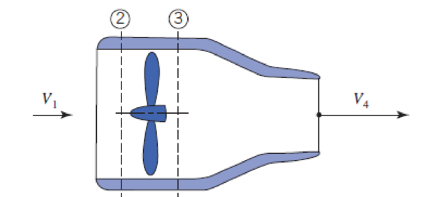
P10.83
Expert Solution & Answer
Want to see the full answer?
Check out a sample textbook solution
Students have asked these similar questions
Q11. Determine the magnitude of the reaction force at C.
1.5 m
a)
4 KN
D
b)
6.5 kN
c)
8 kN
d)
e)
11.3 KN
20 kN
-1.5 m-
C
4 kN
-1.5 m
B
Mechanical engineering, No
Chatgpt.
please help with this practice problem(not a graded assignment, this is a practice exam), and please explain how to use sohcahtoa
Solve this problem and show all of the work
Chapter 10 Solutions
Fox and McDonald's Introduction to Fluid Mechanics
Ch. 10 - The geometry of a centrifugal water pump is r1 =...Ch. 10 - Find the resulting -groups when (a) D, , and Q or...Ch. 10 - Consider the centrifugal pump impeller dimensions...Ch. 10 - Dimensions of a centrifugal pump impeller areCh. 10 - Dimensions of a centrifugal pump impeller areCh. 10 - The blade is one of a series. Calculate the force...Ch. 10 - This blade is one of a series. What force is...Ch. 10 - A centrifugal water pump, with 15-cm-diameter...Ch. 10 - A centrifugal water pump designed to operate at...Ch. 10 - A series of blades, such as in Example 10.13,...
Ch. 10 - In passing through this blade system, the absolute...Ch. 10 - A centrifugal pump runs at 1750 rpm while pumping...Ch. 10 - A centrifugal water pump designed to operate at...Ch. 10 - Kerosene is pumped by a centrifugal pump. When the...Ch. 10 - In the water pump of Problem 10.8, the pump casing...Ch. 10 - Use data from Appendix C to choose points from the...Ch. 10 - Data from tests of a water suction pump operated...Ch. 10 - A centrifugal pump impeller having r1 = 50 mm, r2...Ch. 10 - A centrifugal pump impeller having dimensions and...Ch. 10 - An axial-flow fan operates in sea-level air at...Ch. 10 - Data measured during tests of a centrifugal pump...Ch. 10 - A small centrifugal pump, when tested at N = 2875...Ch. 10 - If the impeller of Problem 10.20 rotates between...Ch. 10 - At the outlet of a pump impeller of diameter 0.6 m...Ch. 10 - Typical performance curves for a centrifugal pump,...Ch. 10 - A pump with D = 500 mm delivers Q = 0.725 m3/s of...Ch. 10 - At its best efficiency point ( = 0.87), a...Ch. 10 - Using the performance curves in Appendix C, select...Ch. 10 - A pumping system must be specified for a lift...Ch. 10 - A centrifugal water pump operates at 1750 rpm; the...Ch. 10 - A set of eight 30-kW motor-pump units is used to...Ch. 10 - A blower has a rotor with 12-in. outside diameter...Ch. 10 - A centrifugal water pump has an impeller with an...Ch. 10 - Appendix C contains area bound curves for pump...Ch. 10 - Use data from Appendix C to verify the similarity...Ch. 10 - A centrifugal water pump has an impeller with...Ch. 10 - Catalog data for a centrifugal water pump at...Ch. 10 - A 1/3 scale model of a centrifugal water pump...Ch. 10 - Sometimes the variation of water viscosity with...Ch. 10 - A large deep fryer at a snack-food plant contains...Ch. 10 - Data from tests of a pump, with a...Ch. 10 - A four-stage boiler feed pump has suction and...Ch. 10 - A centrifugal pump operating at N = 2265 rpm lifts...Ch. 10 - A centrifugal pump is installed in a piping system...Ch. 10 - Part of the water supply for the South Rim of...Ch. 10 - Consider the flow system shown in Problem 8.94....Ch. 10 - Afire nozzle is supplied through 300 ft of...Ch. 10 - Performance data for a centrifugal fan of 3-ft...Ch. 10 - The performance data of Problem 10.57 are for a...Ch. 10 - Experimental test data for an aircraft engine fuel...Ch. 10 - Preliminary calculations for a hydroelectric power...Ch. 10 - Conditions at the inlet to the nozzle of a Pelton...Ch. 10 - A Francis turbine is to operate under a head of 46...Ch. 10 - A Kaplan (propeller with variable-pitch blades)...Ch. 10 - Francis turbine Units 19, 20, and 21, installed at...Ch. 10 - Measured data for performance of the reaction...Ch. 10 - For a flow rate of 12 L/s and turbine speed of 65...Ch. 10 - The velocity of the water jet driving this impulse...Ch. 10 - An impulse turbine is to develop 15 MW from a...Ch. 10 - An impulse turbine under a net head of 33 ft was...Ch. 10 - The absolute velocities and directions of the jets...Ch. 10 - A fanboat in the Florida Everglades is powered by...Ch. 10 - A jet-propelled aircraft traveling at 225 m/s...Ch. 10 - When an air jet of 1-in.-diameter strikes a series...Ch. 10 - The volume flow rate through the propeller of an...Ch. 10 - A typical American multi blade farm windmill has D...Ch. 10 - An airplane flies at 200 km/h through still air of...Ch. 10 - This ducted propeller unit drives a ship through...Ch. 10 - A model of an American multi blade farm windmill...Ch. 10 - A large Darrieus vertical axis wind turbine was...Ch. 10 - Show that this ducted propeller system when moving...Ch. 10 - This ducted propeller unit (now operating as a...Ch. 10 - What is the maximum power that can be expected...Ch. 10 - If an ideal windmill is operating at best...Ch. 10 - A prototype air compressor with a compression...Ch. 10 - Prob. 89PCh. 10 - We have seen many examples in Chapter 7 of...
Additional Engineering Textbook Solutions
Find more solutions based on key concepts
Sailboat Race Ranking Programming Challenge 7 in Chapter 3 asked you to create an application that tracks the p...
Starting Out With Visual Basic (8th Edition)
Here is the first line of a class declaration. What is the name of the superclass? What is the name of the subc...
Starting Out with Java: From Control Structures through Data Structures (4th Edition) (What's New in Computer Science)
16. In a simple electric circuit, the current (I) must remain below 40 milliarr.ps (I < 40 mA) and must also sa...
Thinking Like an Engineer: An Active Learning Approach (4th Edition)
A function is called once from a program's main function, then it calls itself four times. The depth of recursi...
Starting Out with Python (4th Edition)
CONCEPT QUESTIONS
15.CQ3 The ball rolls without slipping on the fixed surface as shown. What is the direction ...
Vector Mechanics for Engineers: Statics and Dynamics
Describe two properties that each candidate key must satisfy.
Modern Database Management
Knowledge Booster


Learn more about
Need a deep-dive on the concept behind this application? Look no further. Learn more about this topic, mechanical-engineering and related others by exploring similar questions and additional content below.Similar questions
- Solve this problem and show all of the workarrow_forwardaversity of Baoyion aculty of Engineering-AIMusyab Automobile Eng. Dep. Year: 2022-2023, st Course, 1st Attempt Stage: 3rd Subject: Heat Transfer I Date: 2023\01\23- Monday Time: 3 Hours Q4: A thick slab of copper initially at a uniform temperature of 20°C is suddenly exposed to radiation at one surface such that the net heat flux is maintained at a constant value of 3×10⁵ W/m². Using the explicit finite-difference techniques with a space increment of Ax = = 75 mm, determine the temperature at the irradiated surface and at an interior point that is 150 mm from the surface after 2 min have elapsed. Q5: (12.5 M) A) A steel bar 2.5 cm square and 7.5 cm long is initially at a temperature of 250°C. It is immersed in a tank of oil maintained at 30°C. The heat-transfer coefficient is 570 W/m². C. Calculate the temperature in the center of the bar after 3 min. B) Air at 90°C and atmospheric pressure flows over a horizontal flat plate at 60 m/s. The plate is 60 cm square and is maintained at a…arrow_forwardUniversity of Baby on Faculty of Engineering-AIMusyab Automobile Eng. Dep. Year: 2022-2023. 1 Course, 1" Attempt Stage 3 Subject Heat Transfer I Date: 2023 01 23- Monday Time: 3 Hours Notes: Q1: • • Answer four questions only Use Troles and Appendices A) A flat wall is exposed to an environmental temperature of 38°C. The wall is covered with a layer of insulation 2.5 cm thick whose thermal conductivity is 1.4 W/m. C, and the temperature of the wall on the inside of the insulation is 315°C. The wall loses heat to the environment by convection. Compute the value of the convection heat-transfer coefficient that must be maintained on the outer surface of the insulation to ensure that the outer-surface temperature does not exceed 41°C. B) A vertical square plate, 30 cm on a side, is maintained at 50°C and exposed to room air at 20°C. The surface emissivity is 0.8. Calculate the total heat lost by both sides of the plate. (12.5 M) Q2: An aluminum fin 1.5 mm thick is placed on a circular tube…arrow_forward
- Solve this and show all of the workarrow_forwardNeed helparrow_forwardY F1 α В X F2 You and your friends are planning to move the log. The log. needs to be moved straight in the x-axis direction and it takes a combined force of 2.9 kN. You (F1) are able to exert 610 N at a = 32°. What magnitude (F2) and direction (B) do you needs your friends to pull? Your friends had to pull at: magnitude in Newton, F2 = direction in degrees, ẞ = N degarrow_forward
arrow_back_ios
SEE MORE QUESTIONS
arrow_forward_ios
Recommended textbooks for you
 Elements Of ElectromagneticsMechanical EngineeringISBN:9780190698614Author:Sadiku, Matthew N. O.Publisher:Oxford University Press
 Mechanics of Materials (10th Edition)Mechanical EngineeringISBN:9780134319650Author:Russell C. HibbelerPublisher:PEARSON
 Thermodynamics: An Engineering ApproachMechanical EngineeringISBN:9781259822674Author:Yunus A. Cengel Dr., Michael A. BolesPublisher:McGraw-Hill Education
 Control Systems EngineeringMechanical EngineeringISBN:9781118170519Author:Norman S. NisePublisher:WILEY
 Mechanics of Materials (MindTap Course List)Mechanical EngineeringISBN:9781337093347Author:Barry J. Goodno, James M. GerePublisher:Cengage Learning
 Engineering Mechanics: StaticsMechanical EngineeringISBN:9781118807330Author:James L. Meriam, L. G. Kraige, J. N. BoltonPublisher:WILEY
Elements Of Electromagnetics
Mechanical Engineering
ISBN:9780190698614
Author:Sadiku, Matthew N. O.
Publisher:Oxford University Press
Mechanics of Materials (10th Edition)
Mechanical Engineering
ISBN:9780134319650
Author:Russell C. Hibbeler
Publisher:PEARSON
Thermodynamics: An Engineering Approach
Mechanical Engineering
ISBN:9781259822674
Author:Yunus A. Cengel Dr., Michael A. Boles
Publisher:McGraw-Hill Education
Control Systems Engineering
Mechanical Engineering
ISBN:9781118170519
Author:Norman S. Nise
Publisher:WILEY
Mechanics of Materials (MindTap Course List)
Mechanical Engineering
ISBN:9781337093347
Author:Barry J. Goodno, James M. Gere
Publisher:Cengage Learning
Engineering Mechanics: Statics
Mechanical Engineering
ISBN:9781118807330
Author:James L. Meriam, L. G. Kraige, J. N. Bolton
Publisher:WILEY
Fluid Mechanics - Viscosity and Shear Strain Rate in 9 Minutes!; Author: Less Boring Lectures;https://www.youtube.com/watch?v=_0aaRDAdPTY;License: Standard youtube license