
Concept explainers
Videos
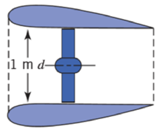
This ducted propeller unit drives a ship through still water at a speed of 4.5 m/s. Within the duct the mean velocity of the water relative to the unit is 15 m/s. Calculate the propulsive force produced by the unit. Calculate the force exerted on the fluid by the propeller. Account for the difference between these forces.
P10.80
Want to see the full answer?
Check out a sample textbook solution
Chapter 10 Solutions
Fox and McDonald's Introduction to Fluid Mechanics
Additional Engineering Textbook Solutions
Starting Out with Java: From Control Structures through Data Structures (4th Edition) (What's New in Computer Science)
Introduction To Programming Using Visual Basic (11th Edition)
Degarmo's Materials And Processes In Manufacturing
Starting Out with C++ from Control Structures to Objects (9th Edition)
Management Information Systems: Managing The Digital Firm (16th Edition)
Modern Database Management


- = The forces F₁ = 590 lb, F₂ = 380 lb, F3 = 240 lb and F 330 lb. Determine the forces in each member of the truss. Use positive values to indicate tension and negative values to indicate compression. a a a D b F₁ A 000 B. 779977 F₂V H G E F4 b BY NC SA 2013 Michael Swanbom Values for dimensions on the figure are given in the following table. Note the figure may not be to scale. Variable Value a 6 ft b 10.1 ft The force in member AB is lb. The force in member AH is lb. The force in member GH is lb. The force in member BH is lb. The force in member BC is lb. The force in member BG is lb. The force in member EG is lb. The force in member CD is lb. The force in member DE is lb. The force in member CE is lb. The force in member CG is lb.arrow_forwardMultiple Choice Circle the best answer to each statement. 1. Which type of surface deviation is controlled by a cy- lindricity tolerance but not by a circularity tolerance? A. B. C. Ovality Taper Lobing D. None of the above 2. When verifying a cylindricity tolerance, the inspec- tion method must be able to collect a set of points and determine the: A. Distance between two coaxial cylinders that con- tain the set of points B. Cylinder that circumscribes the set of points C. Cylinder that inscribes the set of points D. Distance between two coaxial circles that contain the set of points 3. Where Rule #1 applies to a cylindrical regular feature of size, the tolerance value of a cylindricity tolerance applied to the feature of size must be tolerance. A. Less than B. Equal to C. Greater than D. None of the above the size 4. Which of the following modifiers may be applied with a cylindricity tolerance? A. M B. C. ℗ D. Ø 5. Which geometric tolerance can provide an indirect cylindricity…arrow_forwardThe beam AB is attached to the wall in the xz plane by a fixed support at A. A force of F = (−129î + 69.0ĵ + 3591) N is applied to the end of the beam at B. The weight of the beam can be modeled with a uniform distributed load of intensity w = 85.0 N/m acting in the negative z direction along its entire length. Find the support reactions at A. Z с A b a B F y Cc 10 BY NC SA 2016 Eric Davishahl X Values for dimensions on the figure are given in the following. table. Note the figure may not be to scale. Variable Value a 5.60 m b 5.00 m C 3.70 m A II = MA = ( m 2.> ~.> + + k) N k) N-arrow_forward
- need help?arrow_forwardA bent pipe is attached to a wall with brackets as shown. A force of F = 180 lb is applied to the end of the tube with direction indicated by the dimensions in the figure. Determine the support reactions at the brackets B, C, and D. Model these brackets as journal bearings (only force reactions perpendicular to the axis of the tube) and neglect couple moment reactions. Assume the distance between the supports at B and C and the tube bends nearby are negligible such that the support at C is directly above the support at D and the dimension g gives the distance between supports B and C. Enter your answers in Cartesian components. 2013 Michael Swanbom cc 10 BY NC SA g h א B 8° У A C x каж Values for dimensions on the figure are given in the table below. Note the figure may not be to scale. Variable Value a 6.72 in b 11.8 in с 14.8 in d 42.0 in h 26.6 in g 28.0 in → The reaction at B is B = lb. The reaction at C is C = lb. The reaction at D is D = lb. + << + + 2. + + 557 〈んarrow_forwardThe force F1 = 10 kN, F2 = 10 kN, F3 = 10 kN, F4 = 5 KN are acting on the sttructure shown. Determine the forces in the members specified below. Use positive values to indicate tension and negative values to indicate compression. F2 D b F1 F3 C E b F4 b B F a G Values for dimensions on the figure are given in the following table. Note the figure may not be to scale. Variable Value a 3 m b 4 m The force in member BC is KN. The force in member BE is KN. The force in member EF is KN.arrow_forward
- h = The transmission tower is subjected to the forces F₁ 3.6 KN at 50° and F2 = 3.3 kN at = 35°. Determine the forces in members BC, BP, PQ, PC, CD, DP and NP. Use positive values to indicate tension and negative values to indicate compression. 不 кажаж в *а*аж E N M d d IF, c B CENTER LINE S อ K F₂ Kbb cc 10 BY NC SA 2013 Michael Swanbom Values for dimensions on the figure are given in the following table. Note the figure may not be to scale. Variable Value a 1.7 m b 4.9 m с 3 m d 5.2 m h 8.4 m Values for dimensions on the figure are given in the following table. Note the figure may not be to scale. Variable Value a 1.7 m 4.9 m с 3 m d 5.2 m h 8.4 m The force in member BC is KN. The force in member BP is KN. The force in member PQ is KN. The force in member PC is KN. The force in member CD is KN. The force in member DP is KN. The force in member NP is KN.arrow_forwardنصاف Sheet Asteel bar of rectangular cross section with dimension Shown in fig. below. This bar is as Connected toawell. Using welded Join a long the sides als only find the weld size (h). Where: Tall = 35 MN/M² F=213.30 answer/h= 4.04 ☐ Yomm Soomm 100mmarrow_forwardFEAarrow_forward
 Elements Of ElectromagneticsMechanical EngineeringISBN:9780190698614Author:Sadiku, Matthew N. O.Publisher:Oxford University Press
 Mechanics of Materials (10th Edition)Mechanical EngineeringISBN:9780134319650Author:Russell C. HibbelerPublisher:PEARSON
 Thermodynamics: An Engineering ApproachMechanical EngineeringISBN:9781259822674Author:Yunus A. Cengel Dr., Michael A. BolesPublisher:McGraw-Hill Education
 Control Systems EngineeringMechanical EngineeringISBN:9781118170519Author:Norman S. NisePublisher:WILEY
 Mechanics of Materials (MindTap Course List)Mechanical EngineeringISBN:9781337093347Author:Barry J. Goodno, James M. GerePublisher:Cengage Learning
 Engineering Mechanics: StaticsMechanical EngineeringISBN:9781118807330Author:James L. Meriam, L. G. Kraige, J. N. BoltonPublisher:WILEY