
Fox and McDonald's Introduction to Fluid Mechanics
9th Edition
ISBN: 9781118912652
Author: Philip J. Pritchard, John W. Mitchell
Publisher: WILEY
expand_more
expand_more
format_list_bulleted
Concept explainers
Videos
Textbook Question
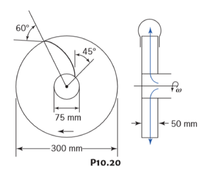
Chapter 10, Problem 20P
A centrifugal pump impeller having dimensions and angles as shown rotates at 500 rpm. Assuming a radial direction of velocity at the blade entrance, calculate the flow rate, the pressure difference between inlet and outlet of blades, and the torque and power required to meet these conditions.
Expert Solution & Answer
Want to see the full answer?
Check out a sample textbook solution
Students have asked these similar questions
The 2-mass system shown below depicts a disk which rotates about its center and has rotational
moment of inertia Jo and radius r. The angular displacement of the disk is given by 0. The spring
with constant k₂ is attached to the disk at a distance from the center. The mass m has linear
displacement & and is subject to an external force u. When the system is at equilibrium, the spring
forces due to k₁ and k₂ are zero. Neglect gravity and aerodynamic drag in this problem. You may
assume the small angle approximation which implies (i) that the springs and dampers remain in
their horizontal / vertical configurations and (ii) that the linear displacement d of a point on the
edge of the disk can be approximated by d≈re.
Ө
K2
www
m
4
Cz
777777
Jo
Make the following assumptions when analyzing the forces and torques:
тв
2
0>0, 0>0, x> > 0, >0
Derive the differential equations of motion for this dynamic system. Start by sketching
LARGE and carefully drawn free-body-diagrams for the disk and the…
A linear system is one that satisfies the principle of superposition. In other words, if an input u₁
yields the output y₁, and an input u2 yields the output y2, the system is said to be linear if a com-
bination of the inputs u = u₁ + u2 yield the sum of the outputs y = y1 + y2.
Using this fact, determine the output y(t) of the following linear system:
given the input:
P(s) =
=
Y(s)
U(s)
=
s+1
s+10
u(t) = e−2+ sin(t)
=e
The manometer fluid in the figure given below is mercury where D = 3 in and h = 1 in. Estimate the volume flow in the tube (ft3/s) if the flowing fluid is gasoline at 20°C and 1 atm. The density of mercury and gasoline are 26.34 slug/ft3 and 1.32 slug/ft3 respectively. The gravitational force is 32.2 ft/s2.
Chapter 10 Solutions
Fox and McDonald's Introduction to Fluid Mechanics
Ch. 10 - The geometry of a centrifugal water pump is r1 =...Ch. 10 - Find the resulting -groups when (a) D, , and Q or...Ch. 10 - Consider the centrifugal pump impeller dimensions...Ch. 10 - Dimensions of a centrifugal pump impeller areCh. 10 - Dimensions of a centrifugal pump impeller areCh. 10 - The blade is one of a series. Calculate the force...Ch. 10 - This blade is one of a series. What force is...Ch. 10 - A centrifugal water pump, with 15-cm-diameter...Ch. 10 - A centrifugal water pump designed to operate at...Ch. 10 - A series of blades, such as in Example 10.13,...
Ch. 10 - In passing through this blade system, the absolute...Ch. 10 - A centrifugal pump runs at 1750 rpm while pumping...Ch. 10 - A centrifugal water pump designed to operate at...Ch. 10 - Kerosene is pumped by a centrifugal pump. When the...Ch. 10 - In the water pump of Problem 10.8, the pump casing...Ch. 10 - Use data from Appendix C to choose points from the...Ch. 10 - Data from tests of a water suction pump operated...Ch. 10 - A centrifugal pump impeller having r1 = 50 mm, r2...Ch. 10 - A centrifugal pump impeller having dimensions and...Ch. 10 - An axial-flow fan operates in sea-level air at...Ch. 10 - Data measured during tests of a centrifugal pump...Ch. 10 - A small centrifugal pump, when tested at N = 2875...Ch. 10 - If the impeller of Problem 10.20 rotates between...Ch. 10 - At the outlet of a pump impeller of diameter 0.6 m...Ch. 10 - Typical performance curves for a centrifugal pump,...Ch. 10 - A pump with D = 500 mm delivers Q = 0.725 m3/s of...Ch. 10 - At its best efficiency point ( = 0.87), a...Ch. 10 - Using the performance curves in Appendix C, select...Ch. 10 - A pumping system must be specified for a lift...Ch. 10 - A centrifugal water pump operates at 1750 rpm; the...Ch. 10 - A set of eight 30-kW motor-pump units is used to...Ch. 10 - A blower has a rotor with 12-in. outside diameter...Ch. 10 - A centrifugal water pump has an impeller with an...Ch. 10 - Appendix C contains area bound curves for pump...Ch. 10 - Use data from Appendix C to verify the similarity...Ch. 10 - A centrifugal water pump has an impeller with...Ch. 10 - Catalog data for a centrifugal water pump at...Ch. 10 - A 1/3 scale model of a centrifugal water pump...Ch. 10 - Sometimes the variation of water viscosity with...Ch. 10 - A large deep fryer at a snack-food plant contains...Ch. 10 - Data from tests of a pump, with a...Ch. 10 - A four-stage boiler feed pump has suction and...Ch. 10 - A centrifugal pump operating at N = 2265 rpm lifts...Ch. 10 - A centrifugal pump is installed in a piping system...Ch. 10 - Part of the water supply for the South Rim of...Ch. 10 - Consider the flow system shown in Problem 8.94....Ch. 10 - Afire nozzle is supplied through 300 ft of...Ch. 10 - Performance data for a centrifugal fan of 3-ft...Ch. 10 - The performance data of Problem 10.57 are for a...Ch. 10 - Experimental test data for an aircraft engine fuel...Ch. 10 - Preliminary calculations for a hydroelectric power...Ch. 10 - Conditions at the inlet to the nozzle of a Pelton...Ch. 10 - A Francis turbine is to operate under a head of 46...Ch. 10 - A Kaplan (propeller with variable-pitch blades)...Ch. 10 - Francis turbine Units 19, 20, and 21, installed at...Ch. 10 - Measured data for performance of the reaction...Ch. 10 - For a flow rate of 12 L/s and turbine speed of 65...Ch. 10 - The velocity of the water jet driving this impulse...Ch. 10 - An impulse turbine is to develop 15 MW from a...Ch. 10 - An impulse turbine under a net head of 33 ft was...Ch. 10 - The absolute velocities and directions of the jets...Ch. 10 - A fanboat in the Florida Everglades is powered by...Ch. 10 - A jet-propelled aircraft traveling at 225 m/s...Ch. 10 - When an air jet of 1-in.-diameter strikes a series...Ch. 10 - The volume flow rate through the propeller of an...Ch. 10 - A typical American multi blade farm windmill has D...Ch. 10 - An airplane flies at 200 km/h through still air of...Ch. 10 - This ducted propeller unit drives a ship through...Ch. 10 - A model of an American multi blade farm windmill...Ch. 10 - A large Darrieus vertical axis wind turbine was...Ch. 10 - Show that this ducted propeller system when moving...Ch. 10 - This ducted propeller unit (now operating as a...Ch. 10 - What is the maximum power that can be expected...Ch. 10 - If an ideal windmill is operating at best...Ch. 10 - A prototype air compressor with a compression...Ch. 10 - Prob. 89PCh. 10 - We have seen many examples in Chapter 7 of...
Additional Engineering Textbook Solutions
Find more solutions based on key concepts
In Program 12-2 , presented earlier in this chapter, what is the base case of the message function?
Starting Out with Python (4th Edition)
Assume a telephone signal travels through a cable at two-thirds the speed of light. How long does it take the s...
Electric Circuits. (11th Edition)
In the following exercises, write a program to carry out the task. The program should use variables for each of...
Introduction To Programming Using Visual Basic (11th Edition)
?.1 Define the different reference meridians that can be used for the direction ofa line.
Elementary Surveying: An Introduction To Geomatics (15th Edition)
Porter’s competitive forces model: The model is used to provide a general view about the firms, the competitors...
Management Information Systems: Managing The Digital Firm (16th Edition)
A file that contains a Flash animation uses the __________ file extension. a. .class b. .swf c. .mp3 d. .flash
Web Development and Design Foundations with HTML5 (8th Edition)
Knowledge Booster


Learn more about
Need a deep-dive on the concept behind this application? Look no further. Learn more about this topic, mechanical-engineering and related others by exploring similar questions and additional content below.Similar questions
- Using the Bernoulli equation to find the general solution. If an initial condition is given, find the particular solution. y' + xy = xy¯¹, y(0) = 3arrow_forwardTest for exactness. If exact, solve. If not, use an integrating factor as given or obtained by inspection or by the theorems in the text. a. 2xydx+x²dy = 0 b. (x2+y2)dx-2xydy = 0 c. 6xydx+5(y + x2)dy = 0arrow_forwardNewton's law of cooling. A thermometer, reading 5°C, is brought into a room whose temperature is 22°C. One minute later the thermometer reading is 12°C. How long does it take until the reading is practically 22°C, say, 21.9°C?arrow_forward
- Solve a. y' + 2xy = ex-x² b. y' + y sin x = ecosx, y(0) = −1 y(0) = −2.5arrow_forward= MMB 241 Tutorial 3.pdf 2/6 90% + + 5. The boat is traveling along the circular path with a speed of v = (0.0625t²) m/s, where t is in seconds. Determine the magnitude of its acceleration when t = 10 s. 40 m v = 0.0625² 6. If the motorcycle has a deceleration of at = (0.001s) m/s² and its speed at position A is 25 m/s, determine the magnitude of its acceleration when it passes point B. .A 90° 300 m n B 2arrow_forward= MMB 241 Tutorial 3.pdf 4/6 67% + 9. The car is traveling along the road with a speed of v = (2 s) m/s, where s is in meters. Determine the magnitude of its acceleration when s = 10 m. v = (2s) m/s 50 m 10. The platform is rotating about the vertical axis such that at any instant its angular position is u = (4t 3/2) rad, where t is in seconds. A ball rolls outward along the radial groove so that its position is r = (0.1+³) m, where t is in seconds. Determine the magnitudes of the velocity and acceleration of the ball when t = 1.5s.arrow_forward
- The population of a certain country is known to increase at a rate proportional to the number of people presently living in the country. If after two years the population has doubled, and after three years the population is 20,000, estimate the number of people initially living in the country.arrow_forward= MMB 241 Tutorial 3.pdf 6/6 100% + | 日 13. The slotted link is pinned at O, and as a result of the constant angular velocity *= 3 rad/s it drives the peg P for a short distance along the spiral guide r = (0.40) m, where 0 is in radians. Determine the radial and transverse components of the velocity and acceleration of P at the instant = 1/3 rad. 0.5 m P r = 0.40 =3 rad/sarrow_forward= MMB 241 Tutorial 3.pdf 1/6 90% + DYNAMICS OF PARTICLES (MMB 241) Tutorial 3 Topic: Kinematics of Particles:- Path and Polar coordinate systems and general curvilinear QUESTIONS motion. 1. Determine the acceleration at s = 2 m if v = (2 s) m/s², where s is in meters. At s = 0, v = 1 m/s. 3 m 2. Determine the acceleration when t=1s if v = (4t2+2) m/s, where t is in seconds. v=(4²+2) m/s 6 marrow_forward
- 5.112 A mounting bracket for electronic components is formed from sheet metal with a uniform thickness. Locate the center of gravity of the bracket. 0.75 in. 3 in. ༧ Fig. P5.112 1.25 in. 0.75 in. y r = 0.625 in. 2.5 in. 1 in. 6 in. xarrow_forward4-105. Replace the force system acting on the beam by an equivalent resultant force and couple moment at point B. A 30 in. 4 in. 12 in. 16 in. B 30% 3 in. 10 in. 250 lb 260 lb 13 5 12 300 lbarrow_forwardSketch and Describe a hatch coaming and show how the hatch coamings are framed in to ships strucure?arrow_forward
arrow_back_ios
SEE MORE QUESTIONS
arrow_forward_ios
Recommended textbooks for you
 Elements Of ElectromagneticsMechanical EngineeringISBN:9780190698614Author:Sadiku, Matthew N. O.Publisher:Oxford University Press
 Mechanics of Materials (10th Edition)Mechanical EngineeringISBN:9780134319650Author:Russell C. HibbelerPublisher:PEARSON
 Thermodynamics: An Engineering ApproachMechanical EngineeringISBN:9781259822674Author:Yunus A. Cengel Dr., Michael A. BolesPublisher:McGraw-Hill Education
 Control Systems EngineeringMechanical EngineeringISBN:9781118170519Author:Norman S. NisePublisher:WILEY
 Mechanics of Materials (MindTap Course List)Mechanical EngineeringISBN:9781337093347Author:Barry J. Goodno, James M. GerePublisher:Cengage Learning
 Engineering Mechanics: StaticsMechanical EngineeringISBN:9781118807330Author:James L. Meriam, L. G. Kraige, J. N. BoltonPublisher:WILEY
Elements Of Electromagnetics
Mechanical Engineering
ISBN:9780190698614
Author:Sadiku, Matthew N. O.
Publisher:Oxford University Press
Mechanics of Materials (10th Edition)
Mechanical Engineering
ISBN:9780134319650
Author:Russell C. Hibbeler
Publisher:PEARSON
Thermodynamics: An Engineering Approach
Mechanical Engineering
ISBN:9781259822674
Author:Yunus A. Cengel Dr., Michael A. Boles
Publisher:McGraw-Hill Education
Control Systems Engineering
Mechanical Engineering
ISBN:9781118170519
Author:Norman S. Nise
Publisher:WILEY
Mechanics of Materials (MindTap Course List)
Mechanical Engineering
ISBN:9781337093347
Author:Barry J. Goodno, James M. Gere
Publisher:Cengage Learning
Engineering Mechanics: Statics
Mechanical Engineering
ISBN:9781118807330
Author:James L. Meriam, L. G. Kraige, J. N. Bolton
Publisher:WILEY
Fluid Mechanics - Viscosity and Shear Strain Rate in 9 Minutes!; Author: Less Boring Lectures;https://www.youtube.com/watch?v=_0aaRDAdPTY;License: Standard youtube license