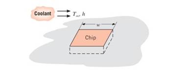
A square isothermal chip is of width w = 5 mm on aside and is mounted in a substrate such that its side andback surfaces are well insulated; the front surface isexposed to the how of a coolant at T ∞ = 15 ° C . Frontreliability considerations, the chip temperature must notexceed T = 85 ° C . If the coolant is air and the corresponding convectioncoefficient is h = 200 W/m 2 ⋅ K , what is the maximumallowable chip power? If the coolant is a dielectricliquid for which h = 300 W/m 2 ⋅ K , what is the maximum allowable power?
A square isothermal chip is of width w = 5 mm on aside and is mounted in a substrate such that its side andback surfaces are well insulated; the front surface isexposed to the how of a coolant at T ∞ = 15 ° C . Frontreliability considerations, the chip temperature must notexceed T = 85 ° C . If the coolant is air and the corresponding convectioncoefficient is h = 200 W/m 2 ⋅ K , what is the maximumallowable chip power? If the coolant is a dielectricliquid for which h = 300 W/m 2 ⋅ K , what is the maximum allowable power?
Solution Summary: The author explains the maximum allowable chip power with air and with dielectric liquid as coolant.
A square isothermal chip is of width
w
=
5
mm
on aside and is mounted in a substrate such that its side andback surfaces are well insulated; the front surface isexposed to the how of a coolant at
T
∞
=
15
°
C
. Frontreliability considerations, the chip temperature must notexceed
T
=
85
°
C
. If the coolant is air and the corresponding convectioncoefficient is
h
=
200
W/m
2
⋅
K
, what is the maximumallowable chip power? If the coolant is a dielectricliquid for which
h
=
300
W/m
2
⋅
K
, what is the maximum allowable power?
For the walking-beam mechanism shown in Figure 3, find and plot the x and y coordinates of the
position of the coupler point P for one complete revolution of the crank O2A. Use the coordinate
system shown in Figure 3. Hint: Calculate them first with respect to the ground link 0204 and
then transform them into the global XY coordinate system.
y
-1.75
Ꮎ
Ꮎ
4
= 2.33
0242.22
L4
x
AP = 3.06
L2 = 1.0
W2
31°
B
03 L3 = 2.06
P
1
8
5
.06
6
7
P'
The link lengths, gear ratio (2), phase angle (Ø), and the value of 02 for some geared five bar
linkages are defined in Table 2. The linkage configuration and terminology are shown in Figure
2. For the rows assigned, find all possible solutions for angles 03 and 04 by the vector loop
method. Show your work in details: vector loop, vector equations, solution procedure.
Table 2
Row
Link 1 Link 2
Link 3
Link 4
Link 5
λ
Φ
Ө
a
6
1
7
9
4
2
30°
60°
P
y 4
YA
B
b
R4
R3
YA
A
Gear ratio:
a
02
d
05
r5
R5
R2
Phase angle: = 0₂-202
R1
05
02
r2
Figure 2.
04
X
Problem 4
A .025 lb bullet C is fired at end B of the 15-lb slender bar AB. The
bar is initially at rest, and the initial velocity of the bullet is 1500 ft/s
as shown. Assuming that the bullet becomes embedded in the bar,
find (a) the angular velocity @2 of the bar immediately after impact,
and (b) the percentage loss of kinetic energy as a result of the impact.
(c) After the impact, does the bar swing up 90° and reach the
horizontal? If it does, what is its angular velocity at this point?
Answers: (a). @2=1.6 rad/s; (b). 99.6% loss
=
(c). Ah2 0.212 ft. The bar does not reach horizontal.
y
X
4 ft
15 lb
V₁
1500 ft/s
0.025 lb
C
30°7
B
A
Need a deep-dive on the concept behind this application? Look no further. Learn more about this topic, mechanical-engineering and related others by exploring similar questions and additional content below.


 Principles of Heat Transfer (Activate Learning wi...Mechanical EngineeringISBN:9781305387102Author:Kreith, Frank; Manglik, Raj M.Publisher:Cengage Learning