
Mechanics of Materials, 7th Edition
7th Edition
ISBN: 9780073398235
Author: Ferdinand P. Beer, E. Russell Johnston Jr., John T. DeWolf, David F. Mazurek
Publisher: McGraw-Hill Education
expand_more
expand_more
format_list_bulleted
Concept explainers
Videos
Textbook Question
Chapter 8.2, Problem 11P
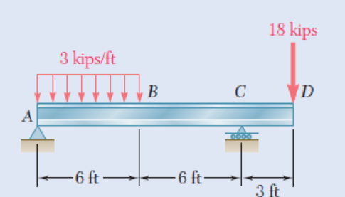
8.9 through 8.14 Each of the following problems refers to a rolled-steel shape selected in a problem of Chap. 5 to support a given loading at a minimal cost while satisfying the requirement σm ≤ σall. For the selected design, determine (a) the actual value of σm in the beam, (b) the maximum value of the principal stress σmax at the junction of a flange and the web.
8.11 Loading of Prob. 5.75 and selected S12 × 31.8 shape.
Fig. P5.75
Expert Solution & Answer
Want to see the full answer?
Check out a sample textbook solution
Students have asked these similar questions
Airplanes A and B, flying at constant velocity and at the same altitude, are tracking the eye
of hurricane C. The relative velocity of C with respect to A is 300 kph 65.0° South of West,
and the relative velocity of C with respect to B is 375 kph 50.0° South of East.
A
120.0 km
B
1N
1. Determine the relative velocity of B with respect to A.
A ground-based radar indicates that hurricane C is moving
at a speed of 40.0 kph due north.
2. Determine the velocity of airplane A.
3. Determine the velocity of airplane B.
Consider that at the start of the tracking expedition, the
distance between the planes is 120.0 km and their initial
positions are horizontally collinear.
4. Given the velocities obtained in items 2 and 3, should
the pilots of planes A and B be concerned whether the
planes will collide at any given time? Prove using
pertinent calculations. (Hint: x = x + vt)
0
Only 100% sure experts solve it correct complete solutions okk don't use guidelines or ai answers okk will dislike okkk.
Solve this probem and show all of the work
Chapter 8 Solutions
Mechanics of Materials, 7th Edition
Ch. 8.2 - A W10 = 39 rolled-steel beam supports a load P as...Ch. 8.2 - Solve Prob. 8.1, assuming that P = 22.5 kips and a...Ch. 8.2 - An overhanging W920 449 rolled-steel beam...Ch. 8.2 - Solve Prob. 8.3, assuming that P = 850 kN and a =...Ch. 8.2 - 8.5 and 8.6 (a) Knowing that all = 160 MPa and all...Ch. 8.2 - 8.5 and 8.6 (a) Knowing that all = 160 MPa and all...Ch. 8.2 - 8.7 and 8.8 (a) Knowing that all = 24 ksi and all...Ch. 8.2 - 8.7 and 8.8 (a) Knowing that all = 24 ksi and all...Ch. 8.2 - 8.9 through 8.14 Each of the following problems...Ch. 8.2 - 8.9 through 8.14 Each of the following problems...
Ch. 8.2 - 8.9 through 8.14 Each of the following problems...Ch. 8.2 - Prob. 12PCh. 8.2 - 8.9 through 8.14 Each of the following problems...Ch. 8.2 - 8.9 through 8.14 Each of the following problems...Ch. 8.2 - Determine the smallest allowable diameter of the...Ch. 8.2 - Determine the smallest allowable diameter of the...Ch. 8.2 - Using the notation of Sec. 8.2 and neglecting the...Ch. 8.2 - The 4-kN force is parallel to the x axis, and the...Ch. 8.2 - The vertical force P1 and the horizontal force P2...Ch. 8.2 - The two 500-lb forces are vertical and the force P...Ch. 8.2 - Prob. 21PCh. 8.2 - Prob. 22PCh. 8.2 - The solid shaft AB rotates at 600 rpm and...Ch. 8.2 - The solid shaft AB rotates at 600 rpm and...Ch. 8.2 - The solid shafts ABC and DEF and the gears shown...Ch. 8.2 - Prob. 26PCh. 8.2 - Prob. 27PCh. 8.2 - Prob. 28PCh. 8.2 - The solid shaft AE rotates at 600 rpm and...Ch. 8.2 - The solid shaft AE rotates at 600 rpm and...Ch. 8.3 - Two 1.2-kip forces are applied to an L-shaped...Ch. 8.3 - Two 1.2-kip forces are applied to an L-shaped...Ch. 8.3 - The cantilever beam AB has a rectangular cross...Ch. 8.3 - 8.34 through 8.36 Member AB has a uniform...Ch. 8.3 - 8.34 through 8.36 Member AB has a uniform...Ch. 8.3 - 8.34 through 8.36 Member AB has a uniform...Ch. 8.3 - Prob. 37PCh. 8.3 - Two forces are applied to the pipe AB as shown....Ch. 8.3 - Several forces are applied to the pipe assembly...Ch. 8.3 - The steel pile AB has a 100-mm outer diameter and...Ch. 8.3 - Three forces are applied to a 4-in.-diameter plate...Ch. 8.3 - The steel pipe AB has a 72-mm outer diameter and a...Ch. 8.3 - A 13-kN force is applied as shown to the...Ch. 8.3 - A vertical force P of magnitude 60 lb is applied...Ch. 8.3 - Three forces are applied to the bar shown....Ch. 8.3 - Prob. 46PCh. 8.3 - Three forces are applied to the bar shown....Ch. 8.3 - Three forces are applied to the bar shown....Ch. 8.3 - Two forces are applied to the small post BD as...Ch. 8.3 - Two forces are applied to the small post BD as...Ch. 8.3 - Three forces are applied to the machine component...Ch. 8.3 - Prob. 52PCh. 8.3 - Three steel plates, each 13 mm thick, are welded...Ch. 8.3 - Three steel plates, each 13 mm thick, are welded...Ch. 8.3 - Two forces P1 and P2 are applied as shown in...Ch. 8.3 - Two forces P1 and P2 are applied as shown in...Ch. 8.3 - Prob. 57PCh. 8.3 - Four forces are applied to a W8 28 rolled-steel...Ch. 8.3 - A force P is applied to a cantilever beam by means...Ch. 8.3 - Prob. 60PCh. 8.3 - A 5-kN force P is applied to a wire that is...Ch. 8.3 - Knowing that the structural tube shown has a...Ch. 8.3 - The structural tube shown has a uniform wall...Ch. 8.3 - The structural tube shown has a uniform wall...Ch. 8 - (a) Knowing that all = 24 ksi and all = 14.5 ksi,...Ch. 8 - Neglecting the effect of fillets and of stress...Ch. 8 - Knowing that rods BC and CD are of diameter 24 mm...Ch. 8 - The solid shaft AB rotates at 450 rpm and...Ch. 8 - A 6-kip force is applied to the machine element AB...Ch. 8 - A thin strap is wrapped around a solid rod of...Ch. 8 - A close-coiled spring is made of a circular wire...Ch. 8 - Forces are applied at points A and B of the solid...Ch. 8 - Knowing that the bracket AB has a uniform...Ch. 8 - For the post and loading shown, determine the...Ch. 8 - Knowing that the structural tube shown has a...Ch. 8 - The cantilever beam AB will be installed so that...
Knowledge Booster


Learn more about
Need a deep-dive on the concept behind this application? Look no further. Learn more about this topic, mechanical-engineering and related others by exploring similar questions and additional content below.Similar questions
- The differential equation of a cruise control system is provided by the following equation: WRITE OUT SOLUTION DO NOT USE A COPIED SOLUTION Find the closed loop transfer function with respect to the reference velocity (vr) . a. Find the poles of the closed loop transfer function for different values of K. How does the poles move as you change K? b. Find the step response for different values of K and plot in MATLAB. What can you observe?arrow_forwardSolve this problem and show all of the workarrow_forwardDetermine the minimum applied force P required to move wedge A to the right. The spring is compressed a distance of 175 mm. Neglect the weight of A and B. The coefficient of static friction for all contacting surface is μs = 0.35. Neglect friction at the rollers. k = = 15 kN/m P A B 10°arrow_forward
- DO NOT COPY SOLUTION- will report The differential equation of a cruise control system is provided by the following equation: Find the closed loop transfer function with respect to the reference velocity (vr) . a. Find the poles of the closed loop transfer function for different values of K. How does the poles move as you change K? b. Find the step response for different values of K and plot in MATLAB. What can you observe?arrow_forwarda box shaped barge 37m long, 6.4 m beam, floats at an even keel draught of 2.5 m in water density 1.025 kg/m3. If a mass is added and the vessel moves into water density 1000 kg/m3, determine the magnitude of this mass if the fore end and aft end draughts are 2.4m and 3.8m respectively.arrow_forwarda ship 125m long and 17.5m beam floats in seawater of 1.025 t/m3 at a draught of 8m. the waterplane coefficient is 0.83, block coefficient 0.759 and midship section area coefficient 0.98. calculate i) prismatic coefficient ii) TPC iii) change in mean draught if the vessel moves into water of 1.016 t/m3arrow_forward
- c. For the given transfer function, find tp, ts, tr, Mp . Plot the resulting step response. G(s) = 40/(s^2 + 4s + 40) handplot only, and solve for eacharrow_forwardA ship of 9000 tonne displacement floats in fresh water of 1.000 t/m3 at a draught 50 mm below the sea water line. The waterplane area is 1650 m2. Calculate the mass of cargo which must be added so that when entering seawater of 1.025 t/m3 it floats at the seawater line.arrow_forwardA ship of 15000 tonne displacement floats at a draught of 7 metres in water of 1.000t/cub. Metre.It is required to load the maximum amount of oil to give the ship a draught of 7.0 metre in seawater ofdensity 1.025 t/cub.metre. If the waterplane area is 2150 square metre, calculate the massof oil requiredarrow_forward
- A ship of 8000 tonne displacement floats in seawater of 1.025 t/m3 and has a TPC of 14. The vessel moves into fresh water of 1.000 t/m3 and loads 300 tonne of oil fuel. Calculate the change in mean draught.arrow_forwardAuto Controls DONT COPY ANSWERS - will report Perform the partial fraction expansion of the following transfer function and find the impulse response: G(s) = (s/2 + 5/3) / (s^2 + 4s + 6) G(s) =( 6s^2 + 50) / (s+3)(s^2 +4)arrow_forwardI submitted the below question and received the answer i copied into this question as well. Im unsure if it is correct, so looking for a checkover. i am stuck on the part tan-1 (0.05) = 0.04996 radians. Just unsure where the value for the radians came from. Just need to know how they got that answer and how it is correct before moving on to the next part. If any of the below information is wrong, please feel free to give me a new answer or an entire new explanation. An Inclining experiment done on a ship thats 6500 t, a mass of 30t was moved 6.0 m transvesly causing a 30 cm deflection in a 6m pendulum, calculate the transverse meta centre height. Here is the step-by-step explanation: Given: Displacement of the ship (W) = 6500 tonnes = 6500×1000=6,500,000kg Mass moved transversely (w) = 30 tonnes=30×1000=30,000kg The transverse shift of mass (d) = 6.0 meters Pendulum length (L) = 6.0 meters Pendulum deflection (x) = 30 cm = 0.30 meters Step 1: Formula for Metacentric Height…arrow_forward
arrow_back_ios
SEE MORE QUESTIONS
arrow_forward_ios
Recommended textbooks for you
 Elements Of ElectromagneticsMechanical EngineeringISBN:9780190698614Author:Sadiku, Matthew N. O.Publisher:Oxford University Press
 Mechanics of Materials (10th Edition)Mechanical EngineeringISBN:9780134319650Author:Russell C. HibbelerPublisher:PEARSON
 Thermodynamics: An Engineering ApproachMechanical EngineeringISBN:9781259822674Author:Yunus A. Cengel Dr., Michael A. BolesPublisher:McGraw-Hill Education
 Control Systems EngineeringMechanical EngineeringISBN:9781118170519Author:Norman S. NisePublisher:WILEY
 Mechanics of Materials (MindTap Course List)Mechanical EngineeringISBN:9781337093347Author:Barry J. Goodno, James M. GerePublisher:Cengage Learning
 Engineering Mechanics: StaticsMechanical EngineeringISBN:9781118807330Author:James L. Meriam, L. G. Kraige, J. N. BoltonPublisher:WILEY
Elements Of Electromagnetics
Mechanical Engineering
ISBN:9780190698614
Author:Sadiku, Matthew N. O.
Publisher:Oxford University Press
Mechanics of Materials (10th Edition)
Mechanical Engineering
ISBN:9780134319650
Author:Russell C. Hibbeler
Publisher:PEARSON
Thermodynamics: An Engineering Approach
Mechanical Engineering
ISBN:9781259822674
Author:Yunus A. Cengel Dr., Michael A. Boles
Publisher:McGraw-Hill Education
Control Systems Engineering
Mechanical Engineering
ISBN:9781118170519
Author:Norman S. Nise
Publisher:WILEY
Mechanics of Materials (MindTap Course List)
Mechanical Engineering
ISBN:9781337093347
Author:Barry J. Goodno, James M. Gere
Publisher:Cengage Learning
Engineering Mechanics: Statics
Mechanical Engineering
ISBN:9781118807330
Author:James L. Meriam, L. G. Kraige, J. N. Bolton
Publisher:WILEY
Everything About COMBINED LOADING in 10 Minutes! Mechanics of Materials; Author: Less Boring Lectures;https://www.youtube.com/watch?v=N-PlI900hSg;License: Standard youtube license