
Concept explainers
Videos
8.9 through 8.14 Each of the following problems refers to a rolled-steel shape selected in a problem of Chap. 5 to support a given loading at a minimal cost while satisfying the requirement σm ≤ σall. For the selected design, determine (a) the actual value of σm in the beam, (b) the maximum value of the principal stress σmax at the junction of a flange and the web.
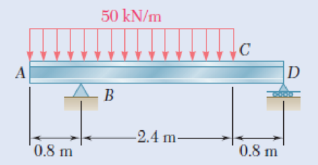
8.10 Loading of Prob. 5.74 and selected W250 × 28.4 shape.
Fig. P5.74
(a)
The actual value of
Answer to Problem 10P
The actual value of
Explanation of Solution
Given information:
Refer to problem 5.74 in chapter 5 in the textbook.
The rolled steel section is
Calculation:
Show the free-body diagram of the beam as in Figure 1.
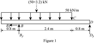
Determine the vertical reaction at point B by taking moment at point D.
Determine the vertical reaction at point D by resolving the vertical component of forces.
Shear force:
Show the calculation of shear force as follows;
Show the calculated shear force values as in Table 1.
| Location (x) m | Shear force (V) kN |
| A | 0 |
| B (Left) | –40 |
| B (Right) | 80 |
| C | –40 |
| D | –40 |
Plot the shear force diagram as in Figure 2.
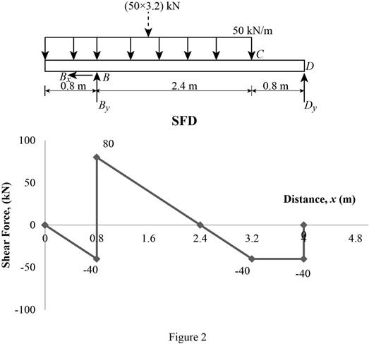
Location of the maximum bending moment:
The maximum bending moment occurs where the shear force changes sign.
Refer to Figure 2;
Use the method of similar triangle.
The maximum bending moment occurs at a distance 2.4 m from the left end of the beam.
Bending moment:
Show the calculation of the bending moment as follows;
Show the calculated bending moment values as in Table 2.
| Location (x) m | Bending moment (M) kN-m |
| A | 0 |
| B | –16 |
| Max BM | 48 |
| C | 32 |
| D | 0 |
Plot the bending moment diagram as in Figure 3.
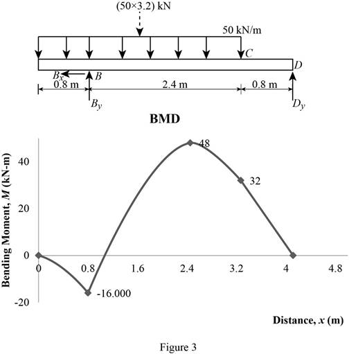
Refer to the Figure 3;
The maximum bending moment in the beam is
Write the section a property for a
| Dimension | Unit( |
| d | 259 mm |
| 102 mm | |
| 10.0 mm | |
| I | |
Here, d is depth of the section,
Find the value of C using the relation:
Substitute
Find the maximum value of normal stress
Here,
Substitute
Thus, the actual value of
(b)
The maximum value of principal stress
Answer to Problem 10P
The maximum value of principal stress
Explanation of Solution
Calculation:
Find the value
Here, c is the centroid and
Substitute
Find the area of flange
Here,
Substitute
Find the centroid of flange
Substitute
Find the first moment about neutral axis
Here,
Substitute
At midspan the value of
Find the maximum value of principal stress
Here, actual value of normal stress
Substitute
Find the shear stress
At midspan the value of
Therefore, the shear stress
At section C,
The shear force at point C is
The bending moment about C is
Find the value of
Substitute
Find the shear stress at b
Substitute
Find the maximum shearing stress (R) using the relation:
Here,
Substitute
Determine the maximum value of the principle stress using the relation:
Here, R is the maximum shearing stress and
Substitute
Based on results,
Select the maximum value of principal stress
Thus, the maximum value of principal stress
Want to see more full solutions like this?
Chapter 8 Solutions
Mechanics of Materials, 7th Edition


- Provide a real-world usage example of the following: Straightness Circularity Parallelism What specific tools, jigs, and other devices are used to control the examples you provided?arrow_forward856 Theory of Machines 5. A shaft carries five masses A, B, C, D and E which revolve at the same radius in planes which are equidistant from one another. The magnitude of the masses in planes A, C and D are 50 kg, 40 kg and 80 kg respectively. The angle between A and C is 90° and that between C and D is 135° Determine the magnitude of the masses in planes B and E and their positions to put the shaft in complete rotating balance. [Ans. 12 kg, 15 kg; 130° and 24° from mass A in anticlockwise direction]arrow_forward2. 3. 4. clockwise from Four masses A, B, C and D revolve at equal radii and are equally spaced along a shaft. The mass B is 7 kg and the radii of C and D make angles of 90° and 240° respectively with the radius of B. Find the magnitude of the masses A, C and D and the angular position of A so that the system may be completely balanced. [Ans. 5 kg: 6 kg; 4.67 kg; 205° from mass B in anticlockwise direction] A rotating shaft carries four masses A, B, C and D which are radially attached to it. The mass centres are 30 mm, 38 mm, 40 mm and 35 mm respectively from the axis of rotation. The masses A, C and D are 7.5 kg. 5 kg and 4 kg respectively. The axial distances between the planes of rotation of A and B is 400 mm and between B and C is 500 mm. The masses A and C are at right angles to each other. Find for a complete balance, 1. the angles between the masses B and D from mass A, 2. the axial distance between the planes of rotation of C and D. 3. the magnitude of mass B. [Ans. 162.5%,…arrow_forward
- 1. Four masses A, B, C and D are attached to a shaft and revolve in the same plane. The masses are 12 kg. 10 kg. 18 kg and 15 kg respectively and their radii of rotations are 40 mm, 50 mm, 60 mm and 30 mm. The angular position of the masses B, C and D are 60°, 135° and 270 from the mass A. Find the magnitude and position of the balancing mass at a radius of 100 mm. [Ans. 7.56 kg: 87 clockwise from A]arrow_forward3. The structure in Figure 3 is loaded by a horizontal force P = 2.4 kN at C. The roller at E is frictionless. Find the axial force N, the shear force V and the bending moment M at a section just above the pin B in the member ABC and illustrate their directions on a sketch of the segment AB. B P D A 65° 65° E all dimensions in meters Figure 3arrow_forward4. The distributed load in Figure 4 varies linearly from 3wo per unit length at A to wo per unit length at B and the beam is built in at A. Find expressions for the shear force V and the bending moment M as functions of x. 3W0 Wo A L Figure 4 2 Barrow_forward
- 1. The beam AB in Figure 1 is subjected to a uniformly distributed load wo = 100 N/m. Find the axial force N, the shear force V and the bending moment M at the point D which is midway between A and B and illustrate their directions on a sketch of the segment DB. wo per unit length A D' B all dimensions in metersarrow_forward5. Find the shear force V and the bending moment M for the beam of Figure 5 as functions of the distance x from A. Hence find the location and magnitude of the maximum bending moment. w(x) = wox L x L Figure 5 Barrow_forwardDry atmospheric air enters an adiabatic compressor at a 20°C, 1 atm and a mass flow rate of 0.3kg/s. The air is compressed to 1 MPa. The exhaust temperature of the air is 70 degrees hottercompared to the exhaust of an isentropic compression.Determine,a. The exhaust temperature of the air (°C)b. The volumetric flow rate (L/s) at the inlet and exhaust of the compressorc. The power required to accomplish the compression (kW)d. The isentropic efficiency of the compressore. An accounting of the exergy entering the compressor (complete Table P3.9) assuming that thedead state is the same as State 1 (dry atmospheric air)f. The exergetic efficiency of the compressorarrow_forward
- A heat pump is operating between a low temperature reservoir of 270 K and a high temperaturereservoir of 340 K. The heat pump receives heat at 255 K from the low temperature reservoir andrejects heat at 355 K to the high temperature reservoir. The heating coefficient of performance ofthe heat pump is 3.2. The heat transfer rate from the low temperature reservoir is 30 kW. The deadstate temperature is 270 K. Determine,a. Power input to the heat pump (kW)b. Heat transfer rate to the high-temperature reservoir (kW)c. Exergy destruction rate associated with the low temperature heat transfer (kW)d. Exergy destruction rate of the heat pump (kW)e. Exergy destruction rate associated with the high temperature heat transfer (kW)f. Exergetic efficiency of the heat pump itselfarrow_forwardRefrigerant 134a (Table B6, p514 of textbook) enters a tube in the evaporator of a refrigerationsystem at 132.73 kPa and a quality of 0.15 at a velocity of 0.5 m/s. The R134a exits the tube as asaturated vapor at −21°C. The tube has an inside diameter of 3.88 cm. Determine the following,a. The pressure drop of the R134a as it flows through the tube (kPa)b. The volumetric flow rate at the inlet of the tube (L/s)c. The mass flow rate of the refrigerant through the tube (g/s)d. The volumetric flow rate at the exit of the tube (L/s)e. The velocity of the refrigerant at the exit of the tube (m/s)f. The heat transfer rate to the refrigerant (kW) as it flows through the tubearrow_forwardWater enters the rigid, covered tank shown in Figure P3.2 with a volumetric flow rate of 0.32L/s. The water line has an inside diameter of 6.3 cm. The air vent on the tank has an inside diameterof 4.5 cm. The water is at a temperature of 30°C and the air in the tank is at atmospheric pressure(1 atm) and 30°C. Determine the air velocity leaving the vent at the instant shown in the figurearrow_forward
 Elements Of ElectromagneticsMechanical EngineeringISBN:9780190698614Author:Sadiku, Matthew N. O.Publisher:Oxford University Press
 Mechanics of Materials (10th Edition)Mechanical EngineeringISBN:9780134319650Author:Russell C. HibbelerPublisher:PEARSON
 Thermodynamics: An Engineering ApproachMechanical EngineeringISBN:9781259822674Author:Yunus A. Cengel Dr., Michael A. BolesPublisher:McGraw-Hill Education
 Control Systems EngineeringMechanical EngineeringISBN:9781118170519Author:Norman S. NisePublisher:WILEY
 Mechanics of Materials (MindTap Course List)Mechanical EngineeringISBN:9781337093347Author:Barry J. Goodno, James M. GerePublisher:Cengage Learning
 Engineering Mechanics: StaticsMechanical EngineeringISBN:9781118807330Author:James L. Meriam, L. G. Kraige, J. N. BoltonPublisher:WILEY